Inflator

a gas inflator and inflator technology, applied in the field of inflators, can solve the problems of complicated structure of manual gas inflators, increased cost, and difficulty in getting co2 sensors, etc., and achieves the effects of simple structure, convenient operation, and reliable performan

Inactive Publication Date: 2016-06-14
LEE WILLIAM
View PDF13 Cites 6 Cited by
  • Summary
  • Abstract
  • Description
  • Claims
  • Application Information

AI Technical Summary

Benefits of technology

[0009]Therefore it is a primary object of the present invention to provide an inflator that not only overcomes shortcomings of conventional ones but also features on simple structure, reliable performance, easy operation, convenient rearming and reduced cost.

Problems solved by technology

Moreover, the structure of the manual gas inflator is complicated and many components required increase the cost.
The CO2 sensor is a special component and is not easy to get.
The disadvantage of the inflation manifold assembly is in that an additional component (such as a color indicator) is required besides replacement of the gas cylinder during the reaming process.
Once the rearming process is interrupted or the color indicator is lost, whether the gas cylinder of the inflator has been used is unable to be confirmed.
Once the rearming process is interrupted or the color indicator is lost, whether the gas cylinder of the inflator has been used is unable to be checked.
When the inflator is operated automatically and the color indicator is not fallen off, whether the gas cylinder is fully-charged is unable to be quickly checked by the appearance.
Thus the cost is increased.
Moreover, the status indicator that indicates whether the gas cylinder has been installed has complicated structure.
Thus the assembly is time-consuming and the cost is further increased.
Thus more assembly processes are required and the defective rate is increased.
Therefore the cost of the product is increased.
Moreover, users are unable to quickly check whether the gas cylinder of the inflator is replaced or not yet during rearming of the inflator.

Method used


Image

  • Inflator
  • Inflator
  • Inflator

Examples


Embodiment Construction

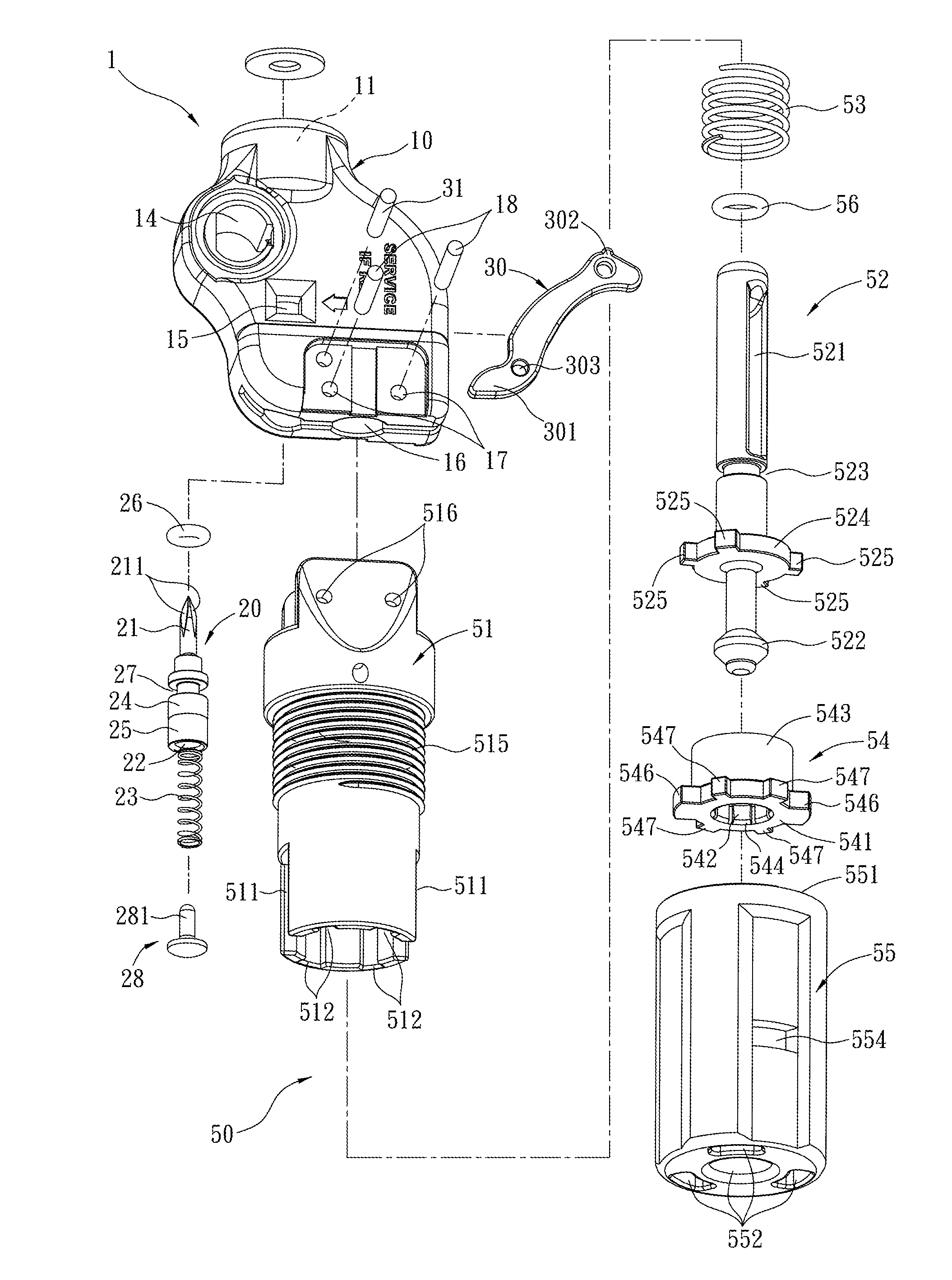
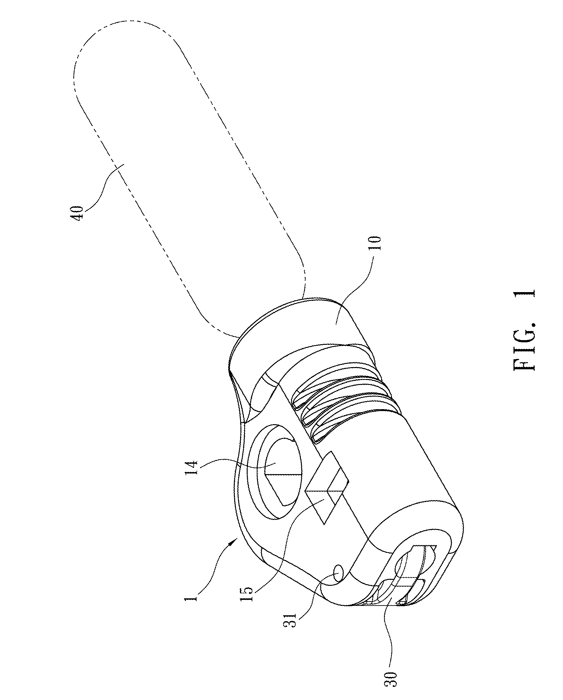
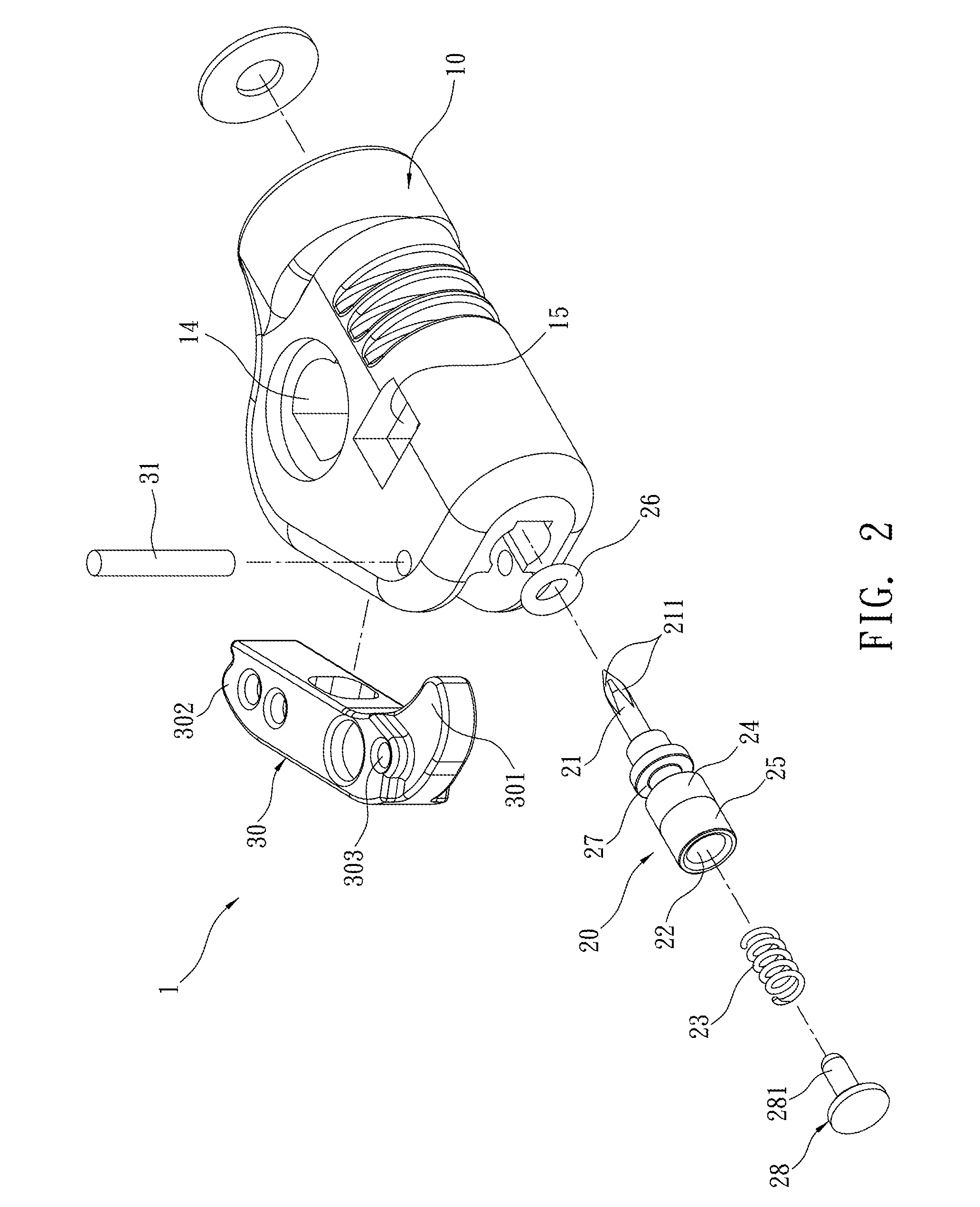
[0030]Refer to FIG. 1 and FIG. 2, an inflator 1 of the present invention includes an inflator body 10, a needle-shaped shaft 20 and a transmission arm 30.

[0031]Refer to FIG. 3 and FIG. 3A, a cylinder housing 11 with an opening facing upward for mounting a gas cylinder 40 (such as CO2 cylinder) is disposed on a top surface of the inflator body 10. A seal 41 of the gas cylinder 40 is facing a bottom surface of the cylinder housing 11. The inflator body 10 further includes a long first channel 12, a chamber 13 therein, and a through hole 14 for connecting an object being inflated (not shown in figure) and located at a side surface thereof. A top end and a bottom end of the first channel 12 are communicating with the cylinder housing 11 and the chamber 13 respectively while the through hole 14 is communicating with one side of the first channel 12. A window 15 is arranged at a front surface and a rear surface of the inflator body 10 respectively. The two windows 15 are arranged symmetri...


PUM


Abstract

An inflator used for inflation of an object such as life jackets, life boats, etc is revealed. A needle-shaped shaft is driven by a transmission arm to pierce a seal of a gas cylinder on the inflator. Thus compressed gas in the gas cylinder is released and flowing through the inflator to inflate the object. The needle-shaped shaft is arranged with two color areas for representing state of the inflator. The color area is displayed through windows of the inflator to show the state now. The inflator features on simple structure, convenience in use, reduced cost and precise movement.

Description

BACKGROUND OF THE INVENTION[0001]The present invention relates to an inflator, especially to an inflator that indicates state and having simple structure.[0002]Generally, water life saving equipment including life jackets, life vests, life rafts, etc. is connected to an inflator with a high pressure gas cylinder for fast inflation and providing gas required for generating buoyancy. The conventional inflator at least includes an inflator body, a pierce pin arranged at and movable with the inflator body, and a rotation arm. While in use, the pierce pin is driven by the rotation arm to pierce a seal of the high pressure gas cylinder. Thus compressed gas in the gas cylinder is released so as to inflation the life saving equipment mentioned above. The inflator is further arranged with an indicator for indicating the state of the inflator and the state of the high pressure gas cylinder. Users can learn the state of the inflator and the gas cylinder.[0003]Refer to U.S. Pat. No. 7,854,347, ...

Claims


Application Information

Patent Timeline
Patent Type & Authority Patents(United States)
IPC IPC(8): B63C9/19B63C9/15
CPCB63C9/155B63C9/19
Inventor LEE, WILLIAM
Owner LEE WILLIAM
Why Eureka
Try Eureka