
Seal assembly for rotary-piston internal-combustion engine

a technology of internal combustion engine and seal assembly, which is applied in the direction of positive displacement engine, machine/engine, mechanical apparatus, etc., can solve the problems of significant stress on the sealing elements, the seal between the rotating block and the stationary case is not optimally designed, and none of the designs achieves wider enlargement and utilization despite the undoubted effect, and achieves high engine performance and high specific parameters. , the effect of effective sealing

Active Publication Date: 2016-06-14
KNOB ENGINES S R O
View PDF17 Cites 0 Cited by
  • Summary
  • Abstract
  • Description
  • Claims
  • Application Information

AI Technical Summary

Benefits of technology

The seal assembly described in this patent is for a rotary piston internal combustion engine and it has several advantages. Firstly, it effectively seals between the rotating block and the stationary case, which means that it can withstand high engine speeds and pressure forces. Secondly, it uses long and planar contact with the rotating block, which reduces demands on the sealing elements and lubrication. Lastly, it achieves a high level of sealing by using multiple seals in both transverse and side direction. The patent also mentions the importance of sealing joints which ensure the seal of clearances between the sealing strips and the stationary case. The use of the seal assembly allows for a simple, production-cheap engine with small dimensions, balanced and silent working, and high specific parameters.

Problems solved by technology

None of those designs has achieved wider enlargement and utilization despite the undoubted potential.
The main reason is that the seal between the rotating block and the stationary case was not optimally designed.
Together with increasing revolutions that leads to significant stress of these sealing elements, to high friction losses and lubrication problems.
That would increase wear and decrease tightness and durability of the sealing strips.
Untightness in the place, where the sealing strips and rings meet, is a problem.

Method used


Image

  • Seal assembly for rotary-piston internal-combustion engine
  • Seal assembly for rotary-piston internal-combustion engine
  • Seal assembly for rotary-piston internal-combustion engine

Examples


Embodiment Construction

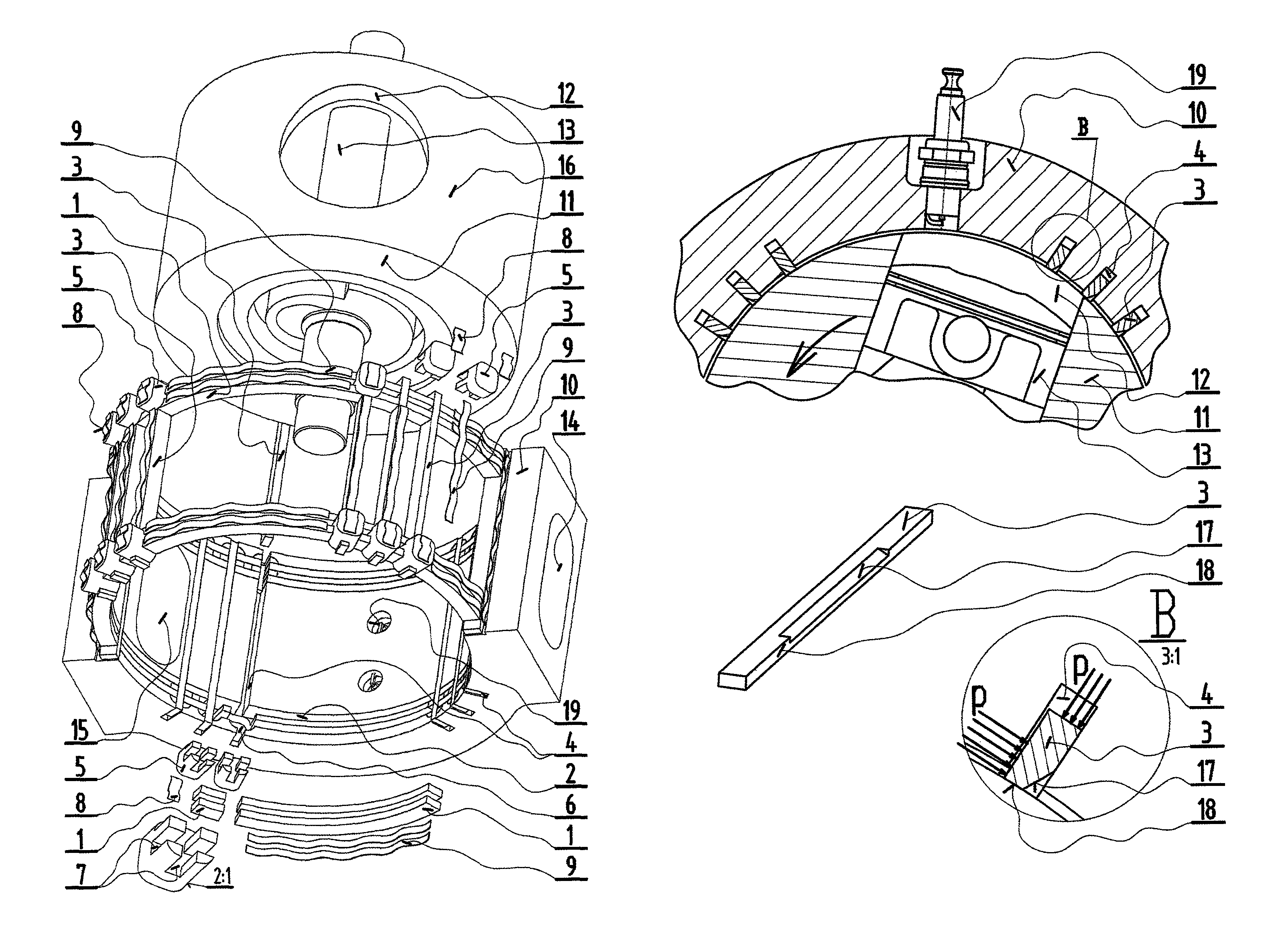
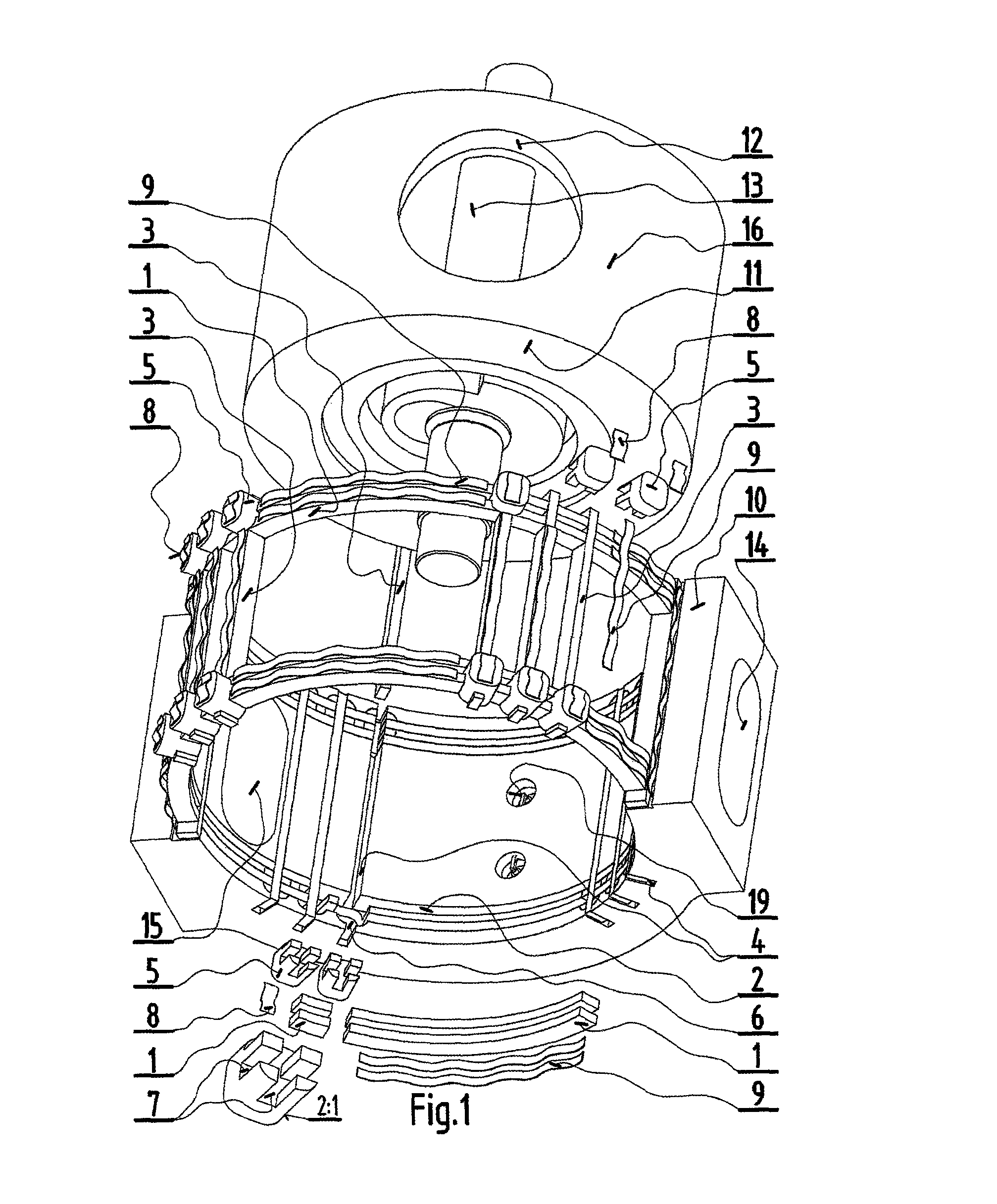
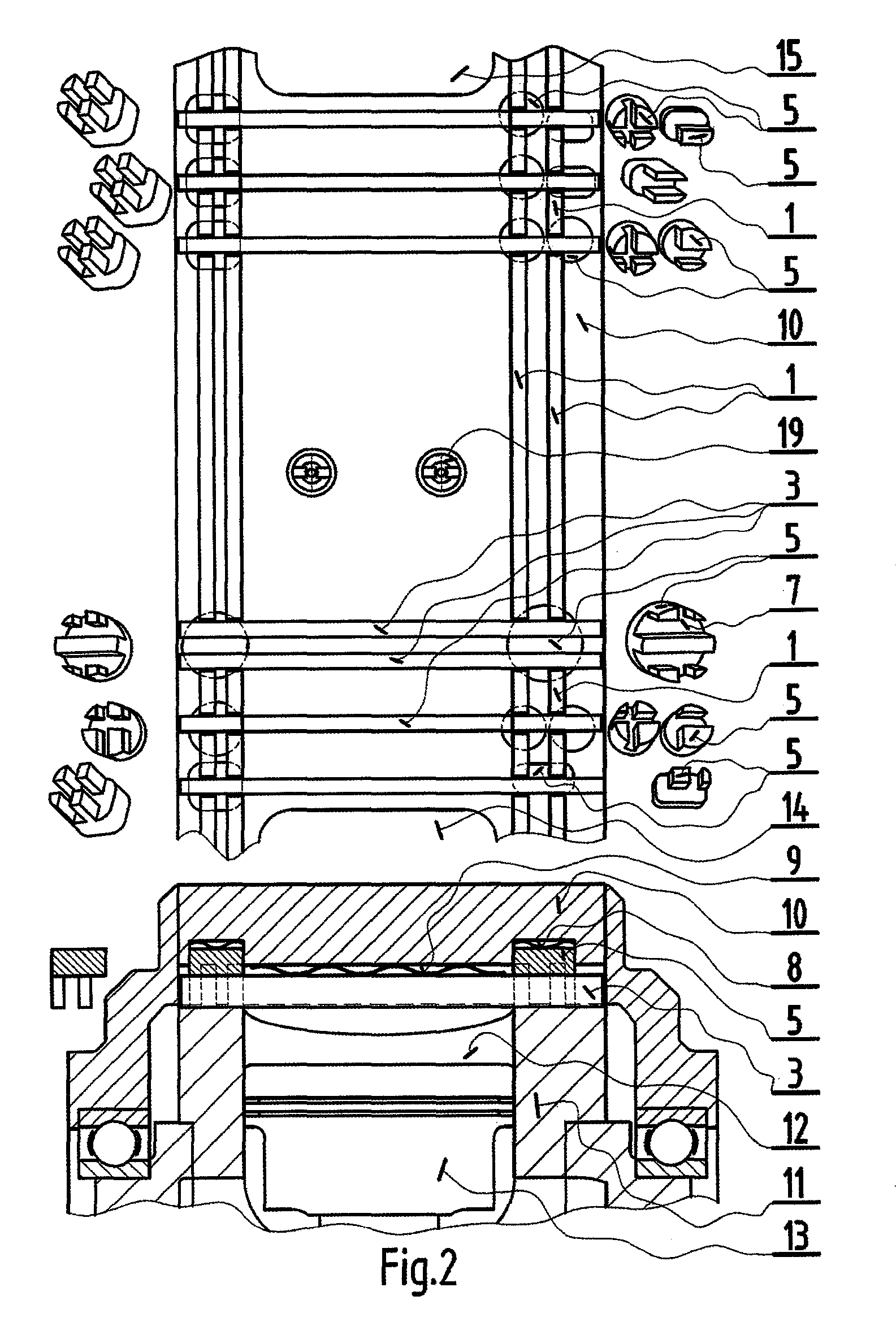
[0019]Model seal for a rotary piston internal combustion engine according to the FIG. 1 comprises circular side sealing segments 1, transverse sealing strips 3, joints 5, springs 8 and other springs 9. All these parts are placed in a stationary case 10, in which a rotating block 11 with radially situated cylinders 12 and pistons 13 is placed. Its outer surface 16 is a rotational cylindrical surface. The stationary case 10 is provided with an intake port 14 and exhaust port 15. Side sealing segments 1 are placed in two rows in circular side grooves 2. Springs 8 and joints 5 are placed in bores 6. Transverse sealing strips 3 are placed in transverse grooves 4 and other springs 9 are placed in transverse grooves 4 and side grooves 2. Between the spark plug 19 and both the intake port 14 and exhaust port 15 there are three transverse strips 3. Joints 5 are provided with notches 7, which side sealing segments 1 and transverse sealing strips 3 reach. The joint 5 connects always one transv...


PUM


Abstract

The invention relates to seal assembly for a rotary piston internal combustion engine comprising a rotating block (11) of a rotational shape with radially situated cylinders (12) with pistons (13) and an outer stationary case (10) with at least one intake port (14) and / or exhaust port (15). The outer surface (16) of the rotating block (11) is a rotational surface with a straight line or curved profile curve, on which transverse and / or side sealing parts, which are placed in the stationary case (10), sit. In circular side grooves (2) there is a side seal consisting of circular side sealing segments (1) that are always placed between neighboring transverse sealing strips (3), which are placed in transverse grooves (4). Those sealing strips (3) go through the side grooves (2) across. In the place, where the side sealing segments (1) and transverse sealing strips (3) meet, there are joints (5) with notches (7) for inserting the side sealing segments (1) and transverse sealing strips (3).

Description

CROSS REFERENCE TO RELATED APPLICATIONS[0001]This application is the US-national stage of PCT application PCT / CZ2013 / 000077 filed 17 Jun. 2013 and claiming the priority of Romanian patent application PV2012-422 itself filed 21 Jun. 2012.TECHNICAL FIELD[0002]The invention relates to embodiment of seal for an internal combustion engine that comprises a rotating block of a rotational shape, with radially situated cylinders with pistons. Outside the rotating cylinder block there is a stationary case with at least one intake and / or exhaust port. The rotating cylinder block together with the stationary case work like a rotary valve.BACKGROUND OF THE INVENTION[0003]There have been designed many engines with a rotating block of a rotational shape with radially situated cylinders with pistons and an outer stationary case with an intake and / or exhaust port. The rotating cylinder block together with the stationary case work like a rotary valve. There are well known designs of two-stroke as wel...

Claims


Application Information

Patent Timeline
Patent Type & Authority Patents(United States)
IPC IPC(8): F01B13/04F02F1/18F02B57/10F02F11/00F01B13/06F02B57/00F02B59/00F02B57/08
CPCF02B59/00F02F1/18F02F11/007F01B13/068F02B57/00F02B57/08
Inventor KNOB, VACLAV
Owner KNOB ENGINES S R O
Learn More