
Concentrated solar tower assembly and method

a concentrated solar and assembly technology, applied in the field of solar power plants, can solve the problems of high labor intensity and cost, dangerous for the safety of construction personnel, and the construction sequence involves a lot of time, so as to reduce the erection activity, save time and money

Active Publication Date: 2016-06-14
GENERAL ELECTRIC TECH GMBH
View PDF29 Cites 1 Cited by
  • Summary
  • Abstract
  • Description
  • Claims
  • Application Information

AI Technical Summary

Benefits of technology

[0007]An object of the present disclosure is to provide construction method of a concentrated solar power plant that reduces the various challenges faced by the industries due the requirements, such as huge labor force, time and cost involved, and also due to pre-construction preparation. Another object of the present disclosure is to provide a construction method that is capable of reducing erection activities at high elevations. Another object of the present disclosure is to provide construction personnel safety. Various other objects and features of the present disclosure will be apparent from the following detailed description and claims.

Problems solved by technology

Constructions of such concentrated solar power plant with such elevated solar tower and such heavy solar receiver is a challenge to industries due the numerous requirements, such as huge labor force, time and cost involved, and also due to pre-construction preparation, such as advance booking of tower cranes due to availability thereof in less numbers, etc.
Such construction sequence involves a lot of time, labor force and cost, as erection activities are done in sequence, erection of the solar tower and then erection of the solar receiver on the top of the solar tower.
Further, the concentrated solar tower construction sequence also involves a lot of erection activities at high elevation and may be very dangerous for construction personnel safety.

Method used


Image

  • Concentrated solar tower assembly and method
  • Concentrated solar tower assembly and method
  • Concentrated solar tower assembly and method

Examples


Embodiment Construction

[0033]For a thorough understanding of the present disclosure, reference is to be made to the following detailed description, including the appended claims, in connection with the above-described drawings. In the following description, for purposes of explanation, numerous specific details are set forth in order to provide a thorough understanding of the present disclosure. It will be apparent, however, to one skilled in the art that the present disclosure can be practiced without these specific details. In other instances, structures and devices are shown in block diagrams form only, in order to avoid obscuring the disclosure. Reference in this specification to “one embodiment,”“an embodiment,”“another embodiment,”“various embodiments,” means that a particular feature, structure, or characteristic described in connection with the embodiment is included in at least one embodiment of the present disclosure. The appearance of the phrase “in one embodiment” in various places in the spec...


PUM

PropertyMeasurementUnit
heightaaaaaaaaaa
weightaaaaaaaaaa
distancesaaaaaaaaaa

Abstract

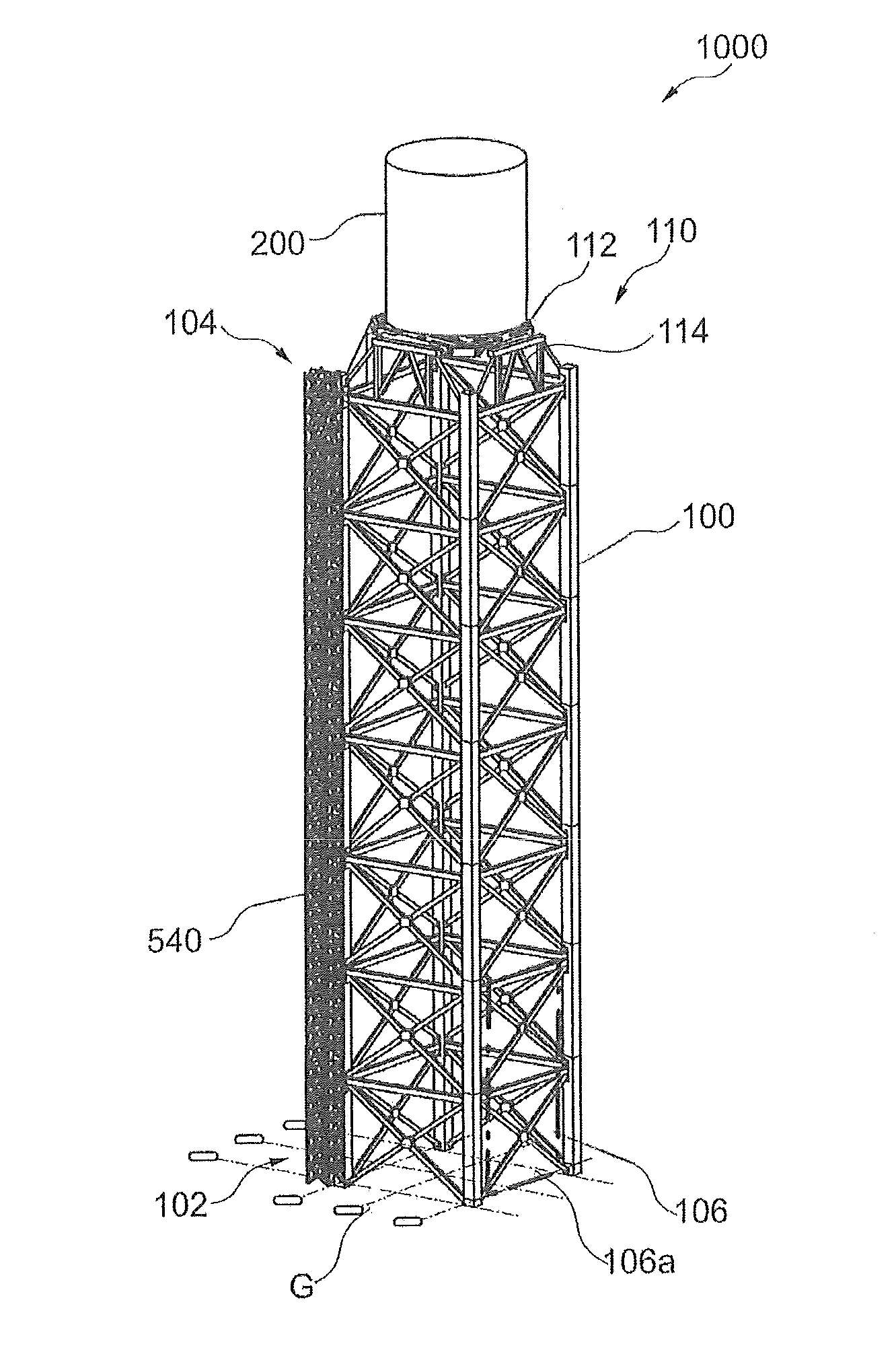
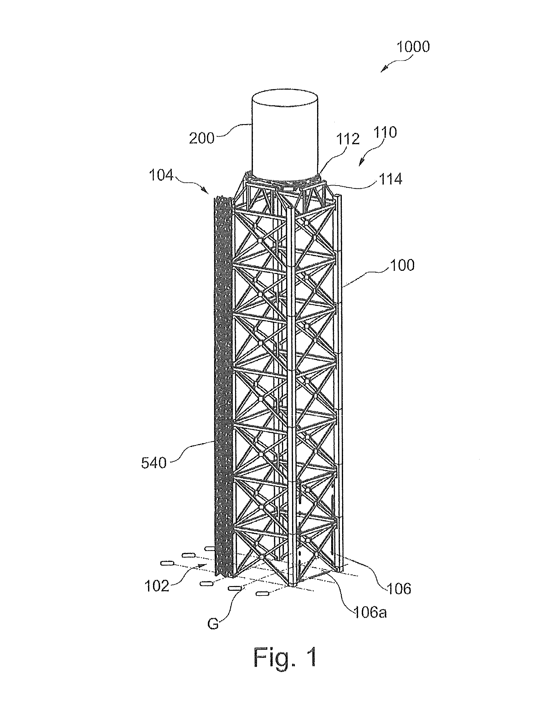
A concentrated solar tower assembly includes a hollow tower structure defining lower and upper portions. The lower portion includes a closable opening region for configuring a closable opening, and the upper portion includes a top gird having inner and outer top grids. The assembly further includes a solar receiver steam generator entirely installed at the ground level G on the inner top grid simultaneous to erection of the tower. The generator on the inner top grid is slidingly directed within the tower from the closable opening to be entirely accommodated therewithin. Thereafter, the generator on the inner top grid is lifted for being placed along the upper portion of the tower.

Description

CROSS-REFERENCE TO RELATED APPLICATIONS[0001]This application claims priority to European Application 12185059.8 filed Sep. 19, 2012, the contents of which are hereby incorporated in its entirety.FIELD OF THE DISCLOSURE[0002]The present disclosure relates to solar power plants, and, more particularly, to a rapid erection of a concentrated solar tower assembly having a solar tower and a solar receiver steam generator, in a concentrated solar power plant.BACKGROUND OF THE DISCLOSURE[0003]A concentrated solar power plant use a solar receiver located at an elevation of a support tower, where the sun rays are focused for utilizing the solar heat to produce electricity. In such plant, over all height of the solar tower and the solar receiver is a critical parameter to have such elevation where maximum sun rays may be focused on the solar receiver. In an example, the solar power plant producing 250 Mega-Watts (MW) of electricity, overall height of the solar tower and the solar receiver may...

Claims


Application Information

Patent Timeline
Patent Type & Authority Patents(United States)
IPC IPC(8): E04H12/34F24J2/02F24S20/30
CPCF24J2/02E04H12/34E04H12/342E04H12/344Y10T29/49355F24S20/30Y02E10/40
Inventor MONTRESOR, PAOLOSACK, MICHAELFRIESS, MARKUS
Owner GENERAL ELECTRIC TECH GMBH
Learn More