
Method, apparatus and computer program for calculating current distribution inside brain

a computer program and brain technology, applied in the field of brain current distribution calculation, can solve the problems of high computational complexity, method accuracy, and restrict the possibility of analyzing brain currents, so as to reduce complexity

Active Publication Date: 2016-06-14
HONDA MOTOR CO LTD
View PDF4 Cites 8 Cited by
  • Summary
  • Abstract
  • Description
  • Claims
  • Application Information

AI Technical Summary

Benefits of technology

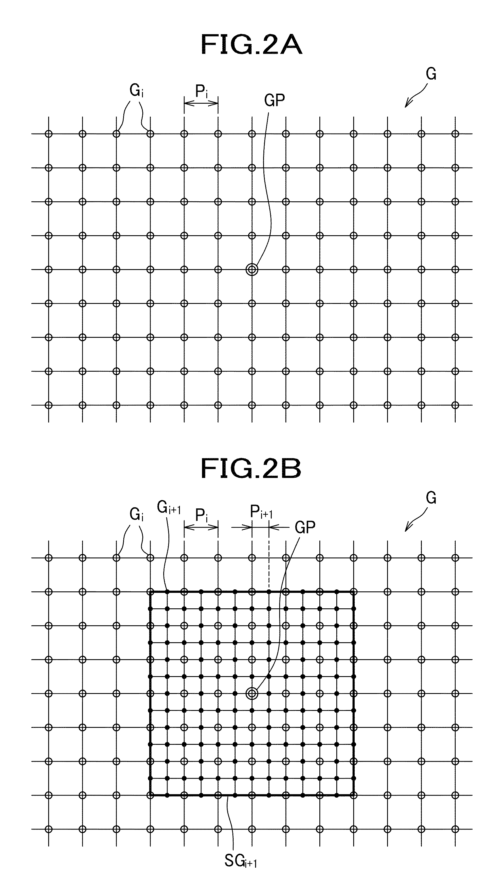
[0013]Accordingly, since a small pitch is applied only to a partial region (subset) and the remaining region (remaining set) has a coarse pitch, the total number of grid points and thus the complexity can be restricted, so that a solution can be obtained in a shorter time. Further, since grid points are set at a smaller pitch in a region where knowing current distribution is desired, current distribution can be obtained at high resolution in the necessary region.
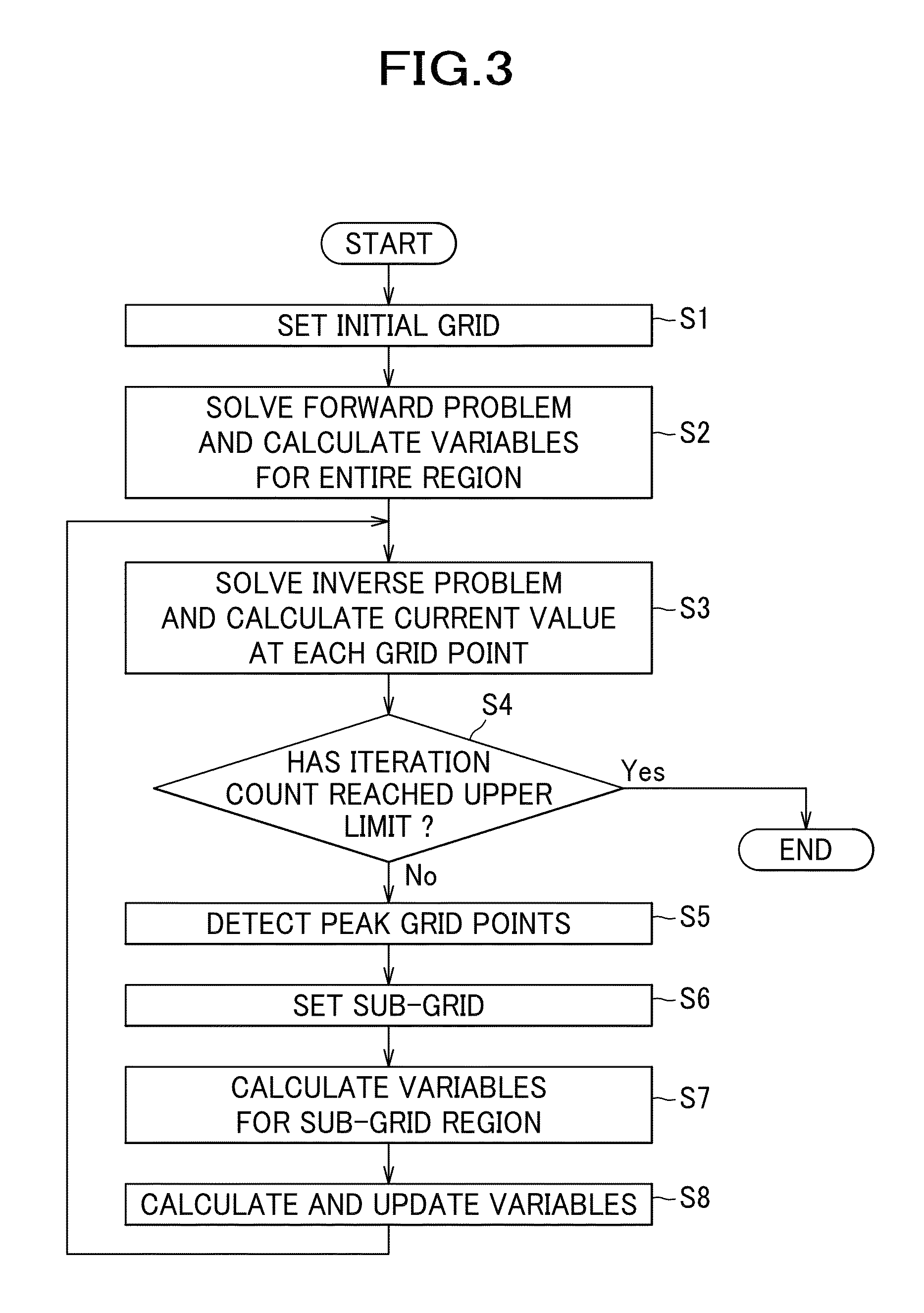
[0017]According to this method, since the forward problem is solved only for the lead field matrix [0 Lsi] having the number of elements corresponding to the increased grid points, and the solved [0 Lsi] is added to the lead field matrix having been calculated in the previous step to obtain [Li Lsi]. This can greatly reduce the complexity compared to solving a forward problem for the lead field matrix for the entire region.
[0019]According to this method, the complexity can be reduced compared to the method for obtaining a gram matrix [Gi+1] for the currently set entire grid by solving [Li+1][Li+1]T.

Problems solved by technology

However, this method has a problem with precision because the actual shape of the head is not reflected in the calculation.
This greatly restricts the possibility that in-brain currents can be analyzed.
However, these numerical analytical methods require a high degree of computational complexity and thus take considerable computation time.
However, this will cause a decrease in the calculation precision.
As a result, a highly precise (high resolution) solution cannot be obtained if the complexity is reduced so much.

Method used


Image

  • Method, apparatus and computer program for calculating current distribution inside brain
  • Method, apparatus and computer program for calculating current distribution inside brain
  • Method, apparatus and computer program for calculating current distribution inside brain

Examples


Embodiment Construction

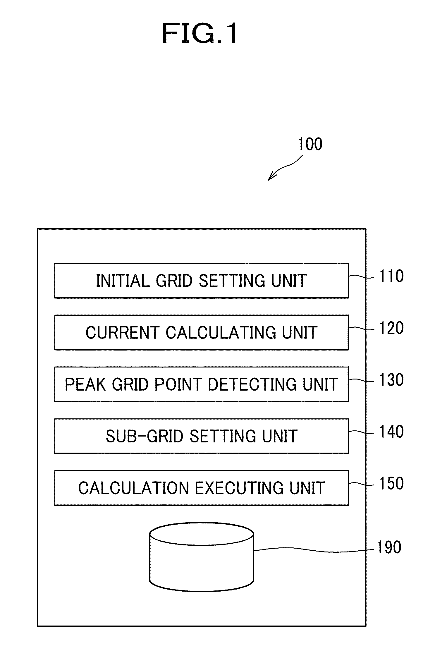
[0029]With reference to the drawings, one embodiment of the present invention will be described in detail. A calculation apparatus 100 for calculating currents inside a brain according to one embodiment calculates current distribution inside the brain, based on an electromagnetic vector [b] (vector representing a set containing information about brain waves or brain's magnetic fields) such as brain waves obtained by measuring electric potentials on the surface of the scalp or brain's magnetic fields obtained by measuring magnetic fields in the vicinity of the scalp, and in particular calculates a current source vector [s] by which the electromagnetic vector [b] has been generated. The number of elements of the electromagnetic vector [b] is the same as the number of sensors, and usually dozens of elements up to several tens of elements are present. Meanwhile, the number of elements of the current source vector [s] is the same as the number of grid points constituting the grid of the ...


PUM

PropertyMeasurementUnit
sizeaaaaaaaaaa
current distributionaaaaaaaaaa
currentaaaaaaaaaa

Abstract

Apparatus for calculating current distribution inside brain includes: initial grid setting unit configured to set grid points constituting grid with predetermined pitch; current calculating unit configured to calculate current value at each grid point based on the electromagnetic information, by solving forward problem to obtain lead field matrix and by solving inverse problem to obtain current source vector; sub-grid setting unit configured to set grid points constituting sub-grid with smaller pitch, only for subset of the previously set grid, based on the current value at each grid point calculated in the preceding current calculating step; and calculation executing unit configured to repeat setting the sub-grid and calculating the current source vector by the sub-grid setting unit and the current calculating unit one or more times, after calculation of current source vector corresponding to the initial grid is executed by the initial grid setting unit and the current calculating unit.

Description

CROSS REFERENCE TO RELATED APPLICATION[0001]This application claims the foreign priority benefit under Title 35, United States Code, §119(a)-(d) of Japanese Patent Application No. 2012-268431 filed on Dec. 7, 2012 in the Japan Patent Office, the disclosure of which is herein incorporated by reference in its entirety.BACKGROUND OF THE INVENTION[0002]1. Technical Field[0003]The present invention relates to a method, an apparatus, and a computer program product for calculating current distribution inside a brain, and in particular to a method, an apparatus, and a computer program product for calculating current distribution inside a brain, by which a solution can be obtained in a short time with a high resolution in-brain current distribution.[0004]2. Description of the Related Art[0005]In recent years, BMI (Brain Machine Interface) has been researched. BMI is a technology for controlling motion of a robot or operation of other devices not by manual control, but by mere thinking about ...

Claims


Application Information

Patent Timeline
Patent Type & Authority Patents(United States)
IPC IPC(8): G01N33/48G01N33/50G06K9/00G06F17/11G06F17/10G06F19/28G06F19/24G06F19/12G16B5/00G16B40/00G16B50/00
CPCG06K9/0057G06F17/11G06F19/24G06F19/28G06F17/10G06F19/12G16B5/00G16B40/00G16B50/00G06F2218/22
Inventor HARUMATSU, MASATOSHIYASHIRO, KATSUYA
Owner HONDA MOTOR CO LTD
Learn More