Active spinal support system

a spinal support system and active technology, applied in the direction of travel articles, protective garments, medical science, etc., can solve the problems of increasing the risk of acute injuries (during extreme events), significant increases in the chance of long-term chronic injuries from normal operations, and the acceleration profile which passes dri may be entirely insufficient to protect a modern, gear-laden vehicle occupant. , to achieve the effect of reducing back fatigue and risk of long-term chronic injuries, no penalty, and safe spinal

Active Publication Date: 2016-06-21
INNOVITAL LLC
View PDF17 Cites 14 Cited by
  • Summary
  • Abstract
  • Description
  • Claims
  • Application Information

AI Technical Summary

Benefits of technology

[0010]The present invention is a wearable spinal support system providing a secondary “backbone” to transmit the additional gear loading to the lower torso (sub lumbar) and / or directly to the seat structure. The system has an upper body adapter engaging the torso of a wearer and a lower body adapter engaging the waist, the upper and lower body adapters joined by an articulated structural column. The structural column is made up of stacked, vertebral elements through each of which an aperture is provided such that a tendon can be fed through the aligned apertures of each arm and the stem. The tendons are fixed at one end and each engaged to a mechanical control element (e.g., an actuator or spring) at the other such that the tension / payout in each tendon is independently variable or managed under direction of a controller receiving sensor feedback in order to support the loaded upper body of the wearer and position it relative to the lower body when desirable according to the controller. The actuators may be electromechanical motors, pneumatically actuated muscles, or other mechanical actuation devices. The present system will automatically adjust the provided support to allow freedom of movement while off-loading the wearer's back through a full spectrum of operational scenarios and motions thereby reducing back fatigue and risk of long-term chronic injuries resulting from dismounted operations or from exposure to shock and vibration while in transit. Additionally, when experiencing a high shock event in a tactical vehicle, such as an underbody blast event, the system actuates to optimally position the body and redirect added equipment mass into the vehicle seat structure and ensure safe spinal loading with no penalty on seat stroking distance.

Problems solved by technology

In addition to the extreme forces resulting from explosive devices, it has been shown that shock and vibration resulting from normal vehicular operations leads to fatigue, back pain, and long-term chronic injuries which result in premature departure of highly trained individuals.
The amount of equipment that soldiers and aviators are required to bear upon their upper torso contributes to the problem.
This can more than double the total mass supported by an individual's spine, which significantly increases the chances of acute injuries (during extreme events) as well as long-term chronic injuries from normal operations.
As a result, an acceleration profile which passes DRI may be entirely insufficient to protect a modern, gear laden vehicle occupant.
These new / updated metrics will have an alarming effect on the perceived performance of currently fielded seating solutions because they will show that many such systems provide inadequate protection.
This is difficult if not impossible since seat stroking distance is already limited and overmatched by blast forces.
One solution to the problem of increased lumbar-supported weight is simply to off-load the spine but this is not practical from an operation perspective because much of this equipment is mission and / or safety critical.
Methods of alternatively supporting the additional equipment / mass by other structure such as the vehicular seat are possible but suffer from concerns of limited mobility and hindered vehicular egress.

Method used


Image

  • Active spinal support system
  • Active spinal support system
  • Active spinal support system

Examples


Embodiment Construction

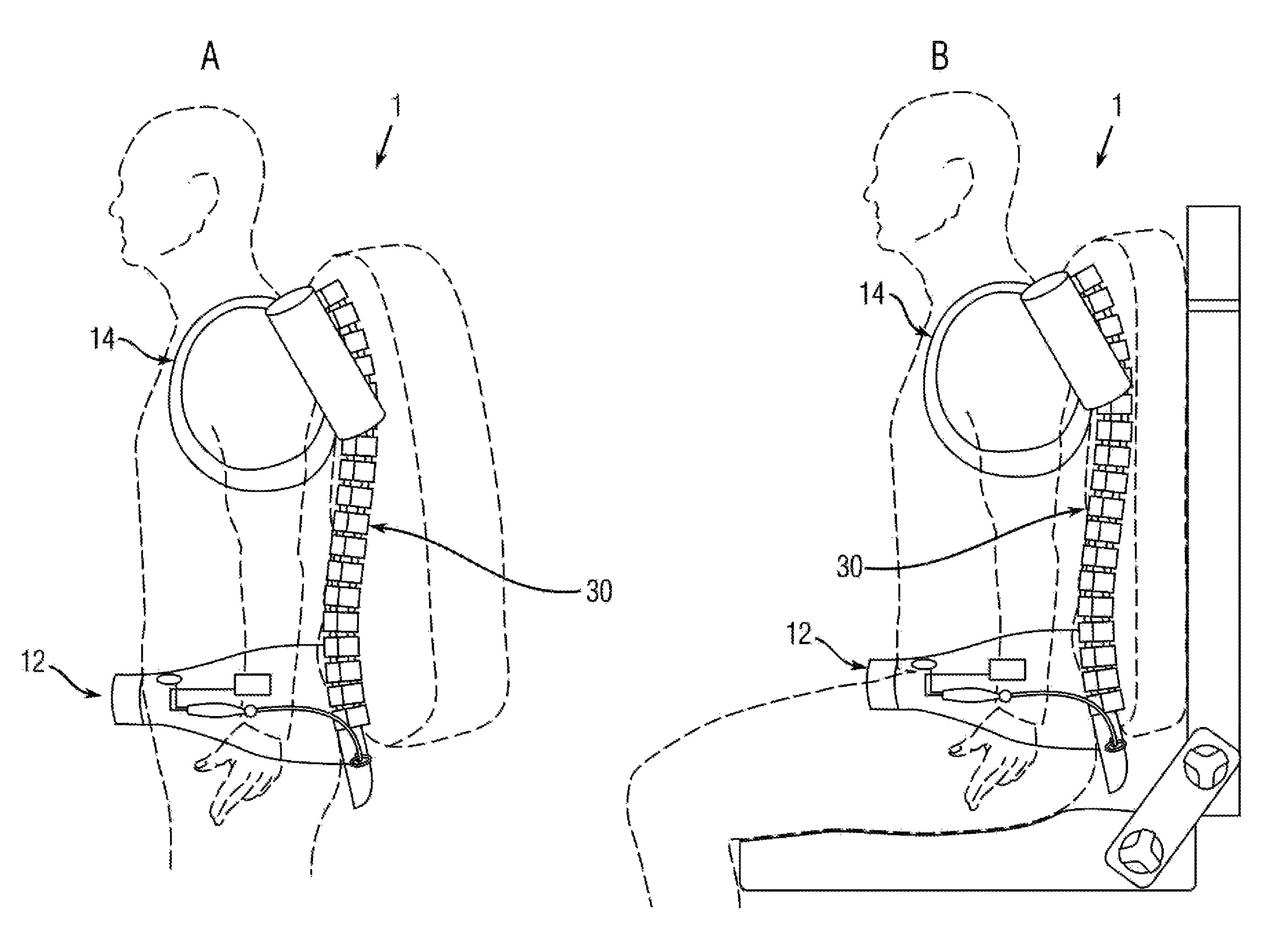
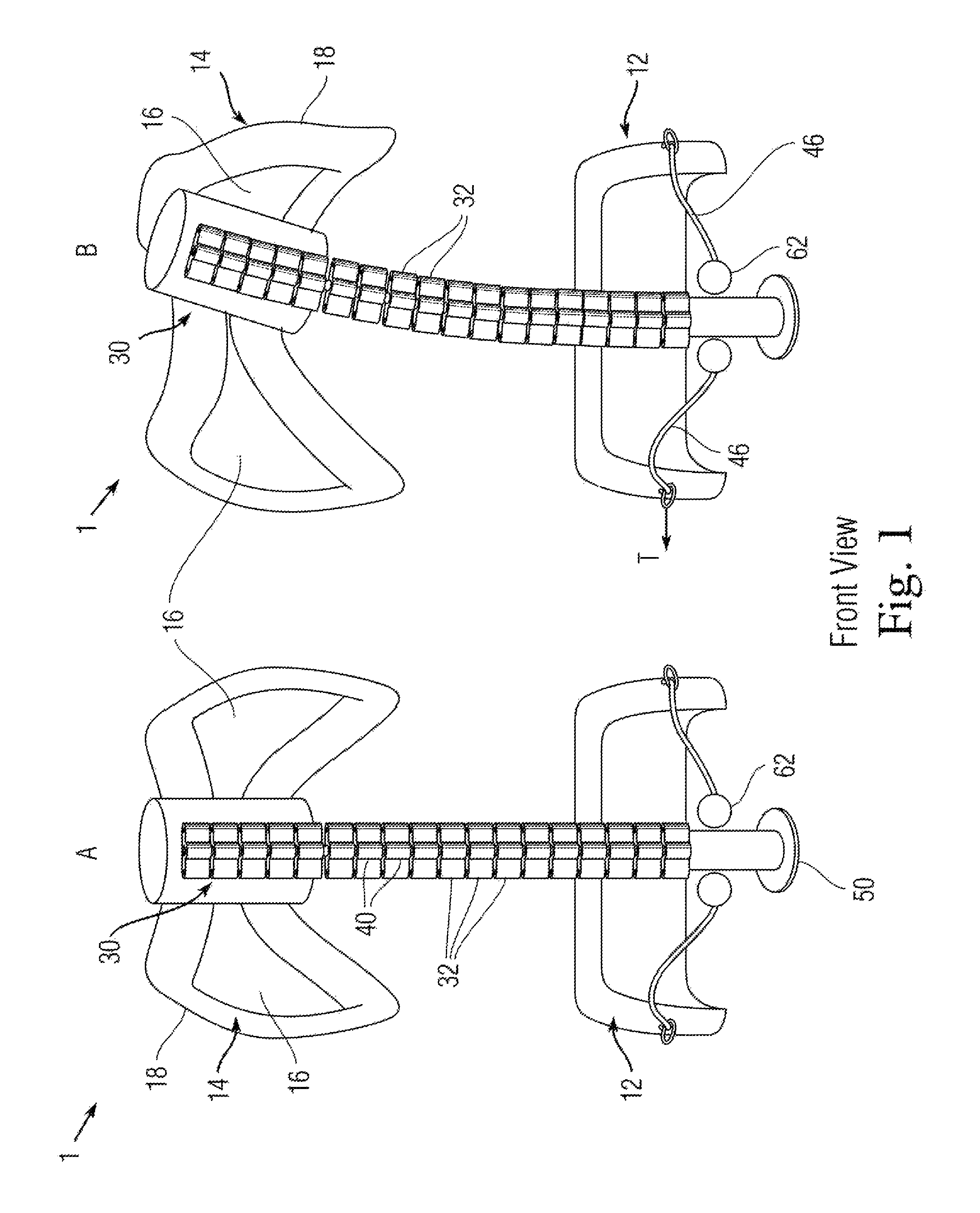
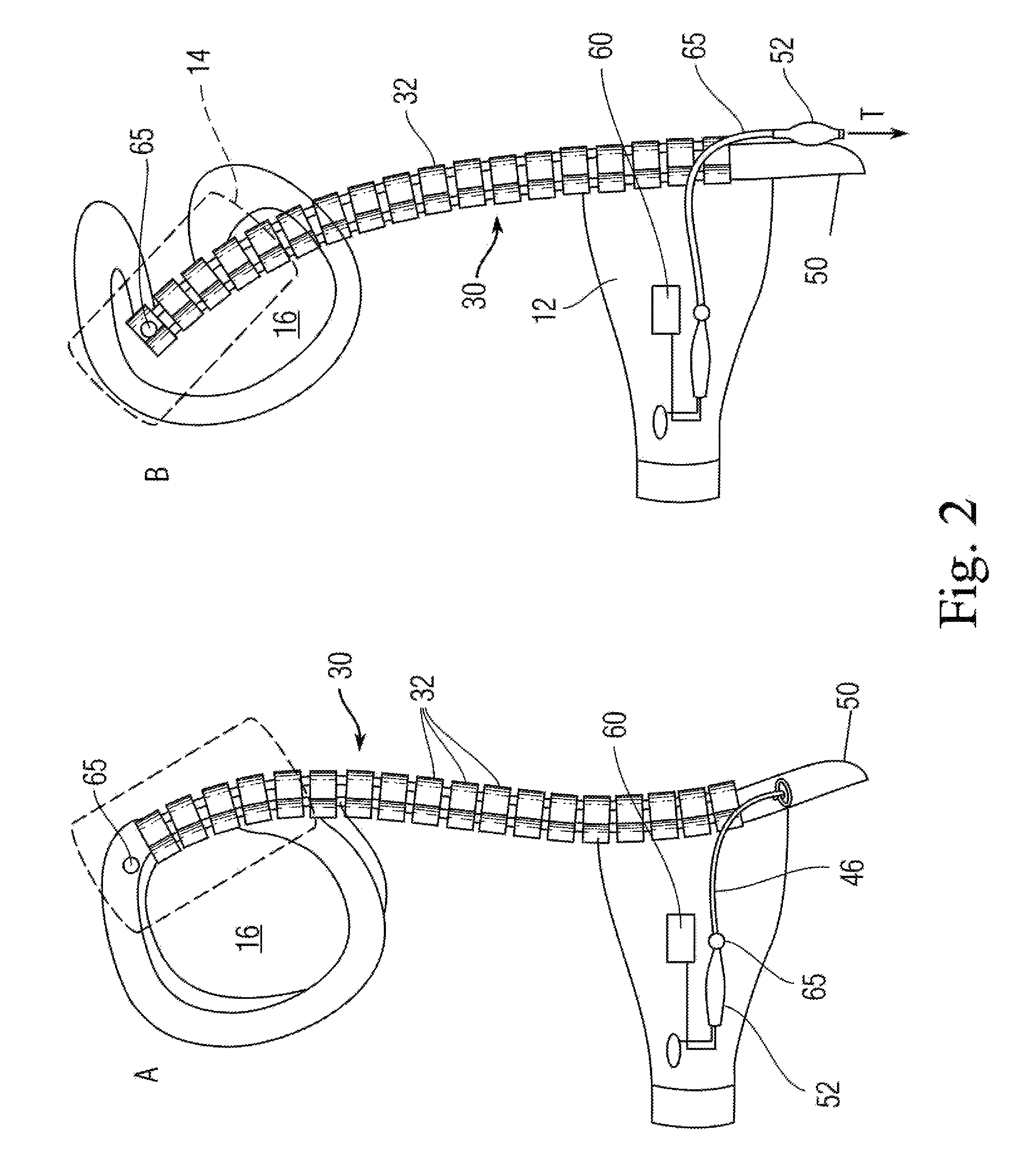
[0019]Disclosed is a human-wearable, spinal support system 1 integrable into any body worn equipment, clothing, gear or load carrying systems for military and non-military applications, including backpacks / rucksacks, jackets, football helmets / pads, body armor, and other clothing and / or gear (collectively “body worn items”) that may also be actively actuated. The system generally incorporates upper and lower body engaging elements joined by the structural backbone element which includes at least one external interoperability fixture for cooperative engagement with a vehicular structure such as a seat or frame bearing point. Under the control of a digital control system which receives information from one or more sensors (e.g., position, tension, acceleration, etc.), an actuated tensioning system adjusts to allow freedom of movement of the wearer while reducing the load of the supported equipment transmitted to the wearer's musculoskeletal system. Then, upon onset of a shock event, th...


PUM


Abstract

A wearable spinal support system having an upper body adapter engaging the head and / or torso of a wearer and a lower body adapter engaging the hips / pelvis, the upper and lower body adapters joined by an articulated structural column. The structural column is made up of stacked vertebral elements each having an aperture provided there through such that a tendon can be fed through the aligned apertures of the vertebral elements. The tendons are fixed at one end and each engaged to mechanical control element at the other end such that the tension / payout in each tendon is independently variable under direction of a controller receiving sensor feedback in order to support the loaded upper body of the wearer and position it relative to the lower body when desirable according to the controller.

Description

CROSS-REFERENCE TO RELATED APPLICATION(S)[0001]The present application derives priority from U.S. Provisional Application Ser. No. 61 / 764,313 filed 13 Feb. 2013.BACKGROUND OF THE INVENTION[0002]1. Field of the Invention[0003]The present invention relates generally to support systems for clothing and body worn equipment, and more particularly, to active support systems for clothing, equipment and / or other body worn items including jackets, backpacks, football helmets / pads, and other military and non-military clothing and gear. The invention actively off-loads bodyworn item loads to reduce back fatigue, and also during a seated shock event for enhanced protection of the wearer.[0004]2. Description of Prior Art[0005]Occupant survivability is a top priority for the design of military ground vehicles as more than 4,400 casualties in recent conflicts, or over 60% of the total casualties, have been the result of the effects of Improvised Explosive Devices (IEDs) on ground vehicles. Operati...

Claims


Application Information

Patent Timeline
Patent Type & Authority Patents(United States)
IPC IPC(8): A45F3/04A42B3/04A41D13/05A45F3/08A45F3/06A61F5/02A45F3/14
CPCA45F3/04A45F3/06A45F3/08A42B3/0473A41D13/0531A61F5/026A45F2003/045A45F2003/144
Inventor HIEMENZ, GREGORY J.KOTHERA, CURT S.SZTEIN, PABLO J.
Owner INNOVITAL LLC
Why Eureka
Try Eureka