
Multi-axis adjustable exercise machine

a multi-axis, adjustable technology, applied in the direction of gymnastic exercise, sport apparatus, cardiovascular exercise devices, etc., can solve the problem that exercisers must exercise for long periods of time, and achieve the effect of increasing the level stimulation of already engaged muscles, increasing energy consumption, and increasing heart ra

Active Publication Date: 2016-06-21
LAGREE TECH INC
View PDF15 Cites 23 Cited by
  • Summary
  • Abstract
  • Description
  • Claims
  • Application Information

AI Technical Summary

Benefits of technology

The present invention is a new exercise machine that can rotate and change its position in different directions, which was previously only possible in a fixed horizontal plane. This new machine allows for more challenging and effective workouts, as it can mimic different positions and angles in real-life situations. This improves the fitness conditioning of the exerciser and helps them achieve better results faster.

Problems solved by technology

Sliding the carriage away from the end of the machine to which the spring resistance is attached creates a workload against which exercises can be safely and beneficially performed.
One major deficiency related to the horizontal support surfaces of traditional exercise machines is that exercisers must exercise for long periods of time in order to achieve significant improvement in cardiovascular efficiency or muscle strength.

Method used


Image

  • Multi-axis adjustable exercise machine
  • Multi-axis adjustable exercise machine
  • Multi-axis adjustable exercise machine

Examples


Embodiment Construction

I. Adjustable Exercise Machine.

A. Overview.

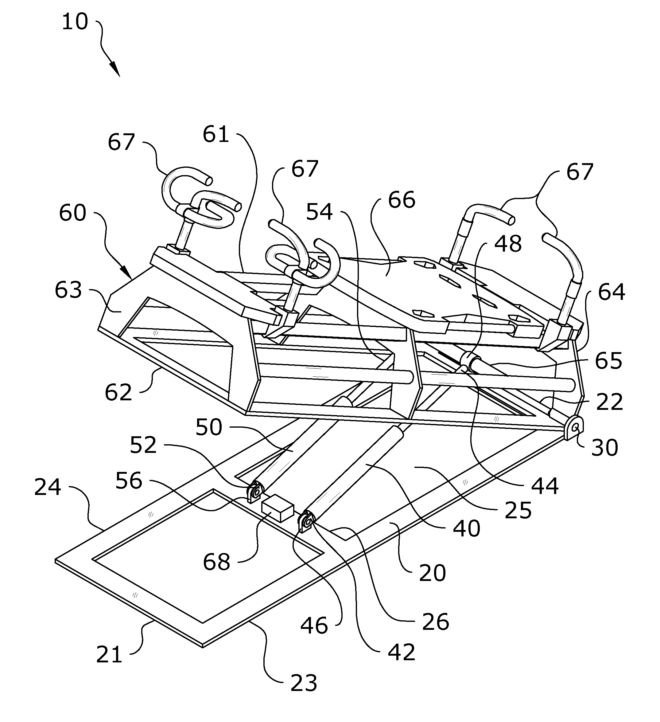
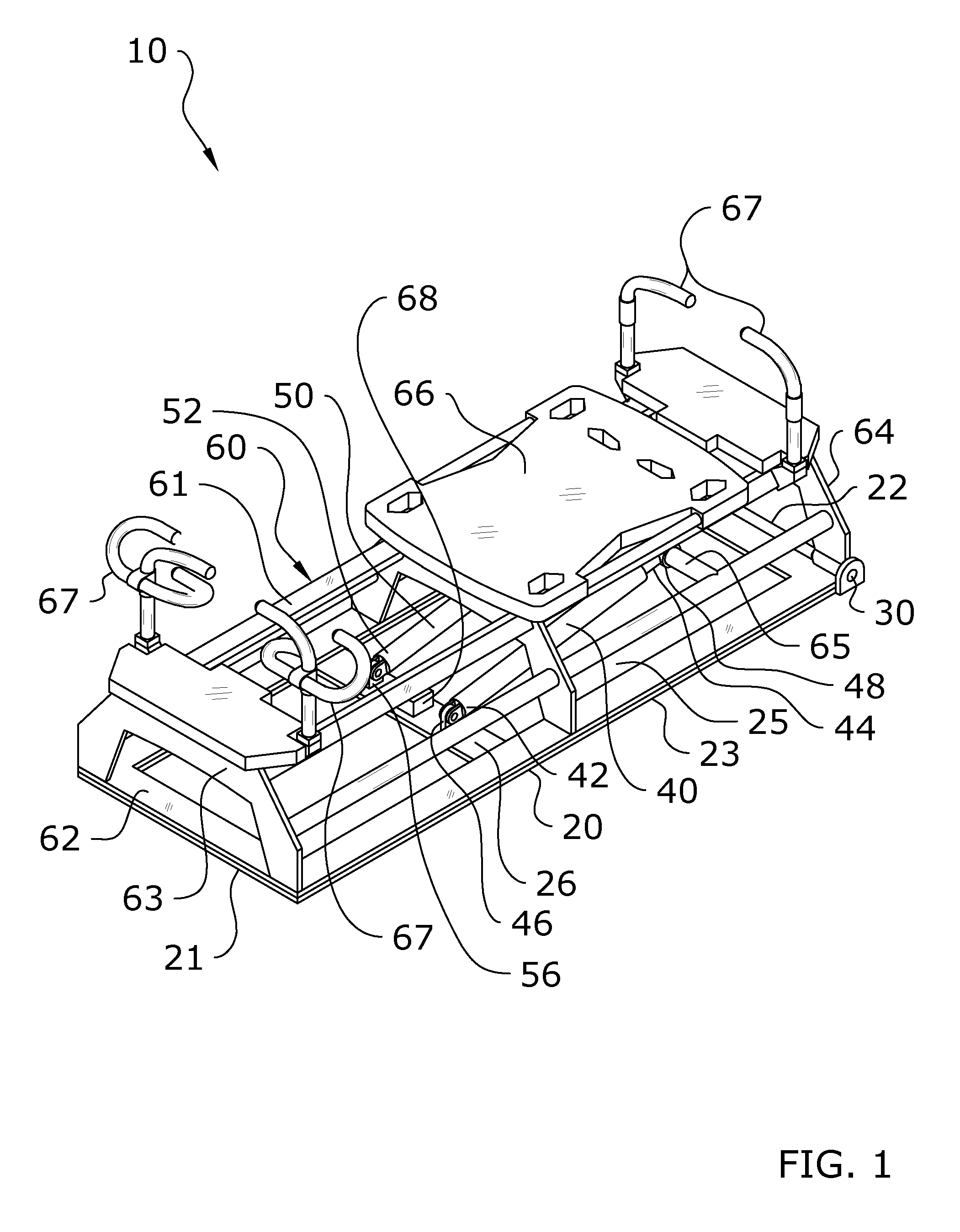
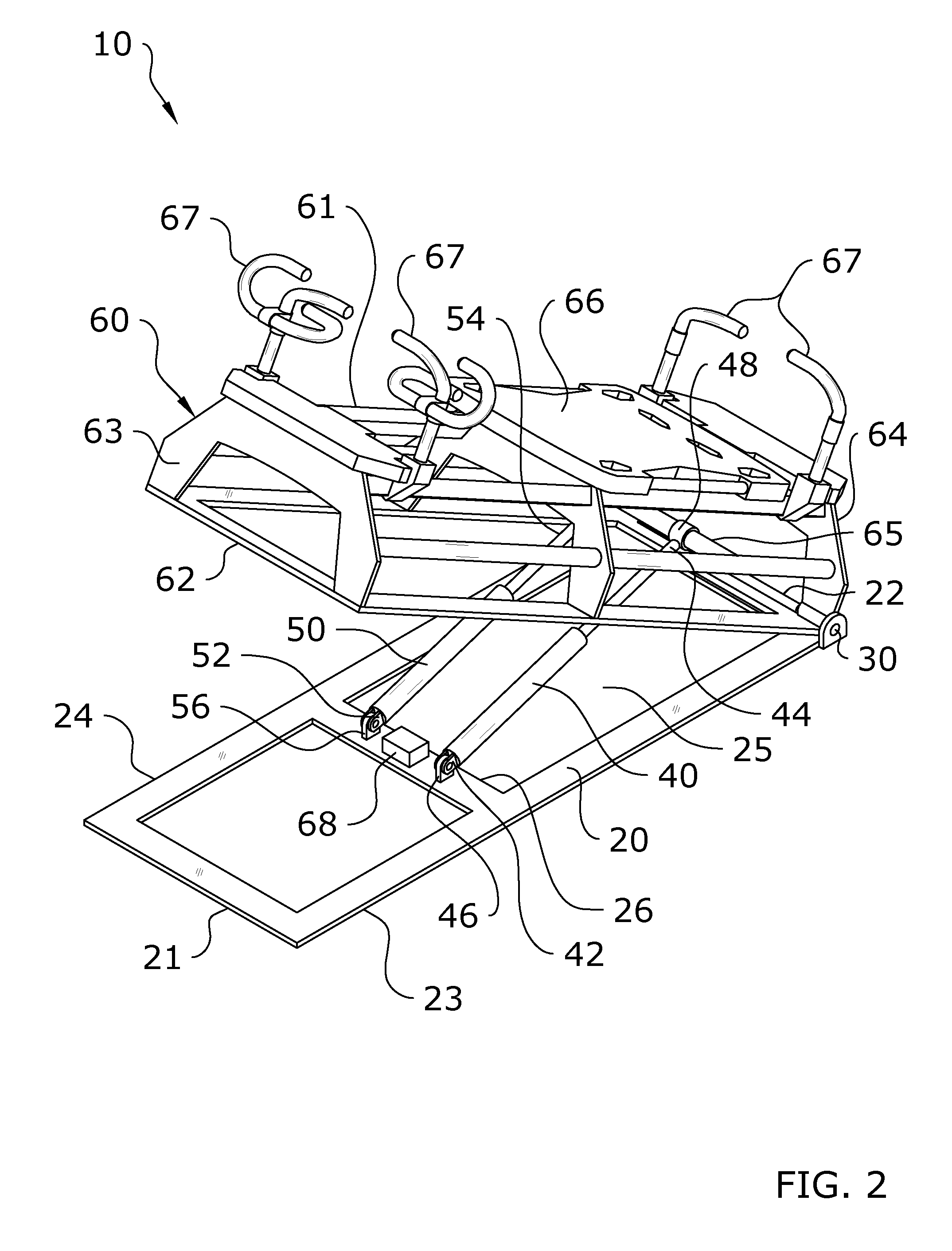
[0087]Turning now descriptively to the drawings, in which similar reference characters denote similar elements throughout the several views, FIGS. 1 through 17 illustrate an adjustable exercise system 10, which comprises a base 20, an exercise machine 60 pivotably connected to the base 20, and one or more actuators 40, 50 for lifting or lowering the exercise machine 60 into varying angles of incline with respect to the base 20. The rear end 22 of the base 20 is generally pivotably connected to the rear end 64 of the exercise machine 60 by a hinge or pivot connectors 30, 32. The front end 63 of the exercise machine 60 may be raised or lowered with respect to the front end 21 of the base 20 by the one or more actuators 40, 50 to achieve varying angles of incline. A controller 70 is also provided which communicates via a wired or wireless communications network 12 with one or more of the adjustable exercise systems 10. Using the controller 70,...


PUM


Abstract

A multi-axis adjustable exercise machine which is pivotable about both a pitch axis and a roll axis with respect to a base for allowing an exerciser to perform a wide range of exercises on a pitched or rolled exercise machine. The multi-axis adjustable exercise machine generally includes an exercise machine which is adjustable with respect to a base. The exercise machine may be pivoted about a roll axis to adjust the roll angle of the exercise machine or may be pivoted about a pitch axis to adjust the pitch angle of the exercise machine. One or more actuators may be connected between the base and the exercise machine to effectuate the pivoting of the exercise machine about either or both axes with respect to the base.

Description

CROSS REFERENCE TO RELATED APPLICATIONS[0001]I hereby claim benefit under Title 35, United States Code, Section 119(e) of U.S. provisional patent application Ser. No. 62 / 004,936 filed May 30, 2014. The 62 / 004,936 application is hereby incorporated by reference into this application.[0002]I hereby claim benefit under Title 35, United States Code, Section 120 of U.S. patent application Ser. No. 14 / 468,958 filed Aug. 26, 2014. This application is a continuation-in-part of the Ser. No. 14 / 468,958 application. The Ser. No. 14 / 468,958 application is hereby incorporated by reference into this application.[0003]I hereby claim benefit under Title 35, United States Code, Section 119(e) of U.S. provisional patent application Ser. No. 61 / 869,904 filed Aug. 26, 2013. The 61 / 869,904 application is hereby incorporated by reference into this application.STATEMENT REGARDING FEDERALLY SPONSORED RESEARCH OR DEVELOPMENT[0004]Not applicable to this application.BACKGROUND OF THE INVENTION[0005]1. Field o...

Claims


Application Information

Patent Timeline
Patent Type & Authority Patents(United States)
IPC IPC(8): A63B24/00A63B21/04A63B21/068A63B21/055A63B21/00A63B21/008
CPCA63B23/0233A63B21/0552A63B24/0084A63B24/0087A63B21/0428A63B21/00069A63B21/068A63B22/0002A63B24/0075A63B22/0089A63B22/0023A63B21/4045A63B21/023A63B22/0012A63B22/0046A63B22/0087A63B21/4033A63B23/0205A63B21/0083A63B2024/0093A63B2208/0204A63B2208/0242A63B2225/50A63B2024/0081A63B2208/0214A63B2208/0219A63B2225/54A63B2230/60A63B21/00065A63B21/00061A63B21/4034A63B21/4043A63B21/4035A63B21/0442A63B22/02A63B22/0605A63B22/0664A63B22/18A63B22/203A63B23/0211A63B23/03508A63B23/03525A63B23/03541A63B23/047A63B23/1209A63B2022/0094A63B2023/003A63B2023/0411A63B21/0087
Inventor LAGREE, SEBASTIEN ANTHONY LOUISCOX, SAMUEL D.REMUND, TODD G.
Owner LAGREE TECH INC
Learn More