
Apparatus and method for learning filling parameters for a clutch

a technology of clutches and apparatuses, applied in mechanical apparatus, clutches, couplings, etc., can solve problems such as system changes, poor shift quality, and filling errors, and achieve the effect of eliminating the need for transmission calibration and greater production tolerances

Active Publication Date: 2016-06-21
DANA BELGIUM
View PDF9 Cites 0 Cited by
  • Summary
  • Abstract
  • Description
  • Claims
  • Application Information

AI Technical Summary

Benefits of technology

[0012]Presently provided by the invention, a device and method for learning filling parameters for a clutch that eliminates a need for transmission calibrations, allows components having greater production tolerances to be used in the clutch, and allows a variety of transmission fluids to be used with the clutch, has surprisingly been discovered.

Problems solved by technology

A problem that remains however, is how to obtain a correct value for each of these parameters.
The correction factors are not in all cases a good representation of the characteristics of the actual system, which can lead to errors in the filling and consequently, poor shift quality.
While generally accurate parameters can be obtained by performing a calibration following production, the system also changes as the friction plates wear, an automatic transmission fluid wears out, and a stiffness of a clutch spring deteriorates.
The current typical calibration process which is used to solve these problems takes a considerable amount of time, and during the calibration process the vehicle cannot be used.
As an amount of the time between recalibrations is not based on the actual condition of the transmission, but rather as a fixed number of operating hours, reducing a number of recalibrations is achieved by imposing limitations on the mechanical system.
Furthermore, only the usage of a single type of transmission fluid is recommended by the manufacturer, as the temperature or viscosity compensation factors are only valid for the recommended type of transmission fluid.
Lack of versatility in this respect can increase ownership and maintenance costs of the vehicle.
Another problem with the current typical calibration process is that the transmission controller is not aware when a bad shift is performed as a result of unsuitable fill parameters.

Method used


Image

  • Apparatus and method for learning filling parameters for a clutch
  • Apparatus and method for learning filling parameters for a clutch
  • Apparatus and method for learning filling parameters for a clutch

Examples


Embodiment Construction

[0026]It is to be understood that the invention may assume various alternative orientations and step sequences, except where expressly specified to the contrary. It is also to be understood that the specific devices and processes illustrated in the attached drawings, and described in the following specification are simply exemplary embodiments of the inventive concepts defined herein. Hence, specific dimensions, directions or other physical characteristics relating to the embodiments disclosed are not to be considered as limiting, unless expressly stated otherwise.

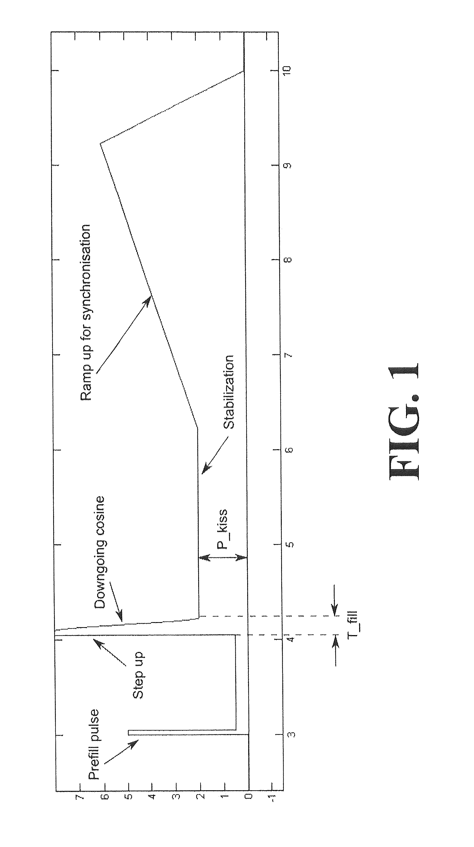
[0027]A process of filling of a clutch is commonly characterized by two main parameters, a fill time and a kiss pressure. These parameters are shown on an exemplary pressure profile, which is illustrated in FIG. 1. A reference of “T_fill” in FIG. 1 indicates the fill time of the exemplary pressure profile, and a reference of “P_kiss” indicates the kiss pressure of the exemplary pressure profile. It should be noted that an ...


PUM


Abstract

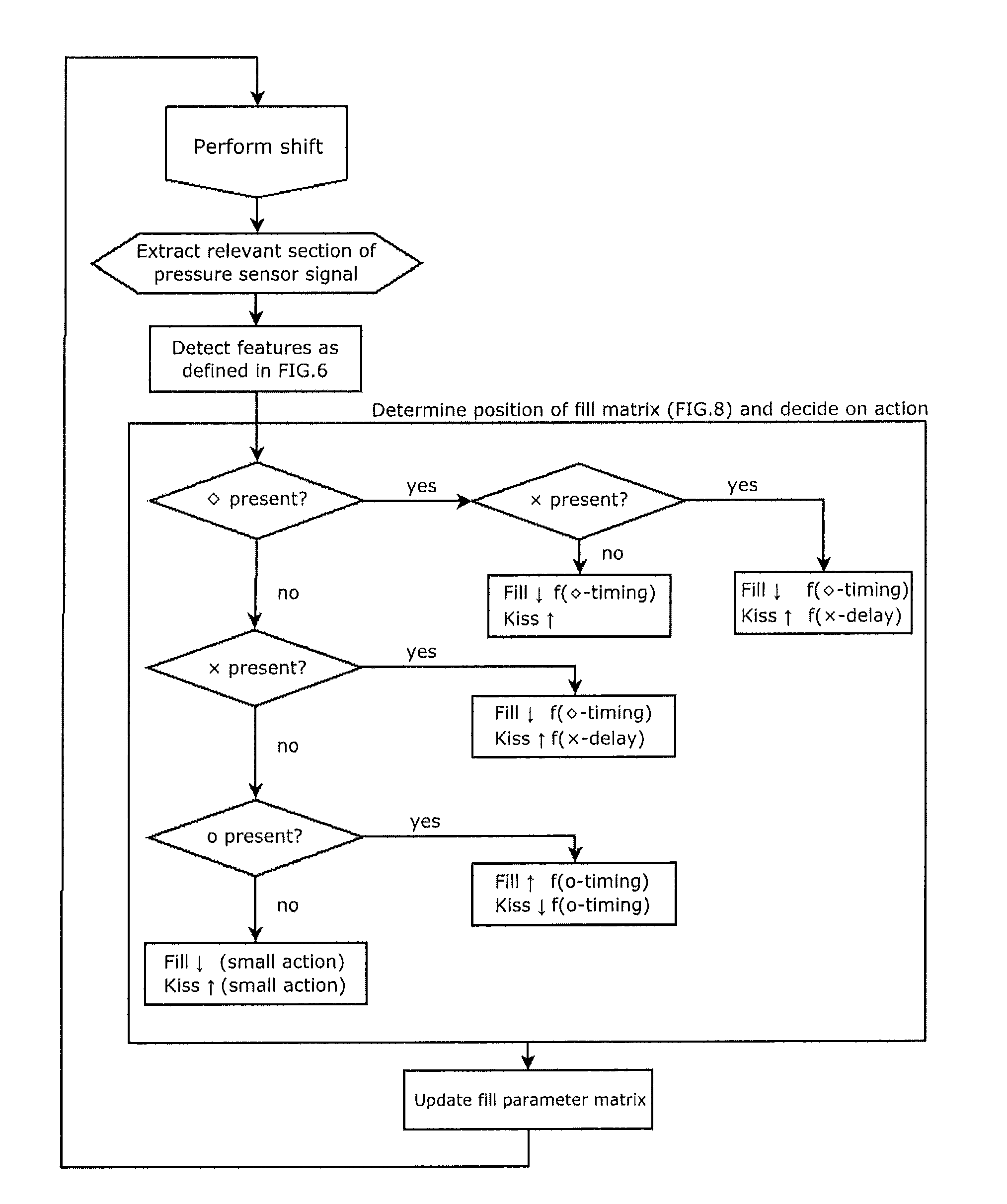
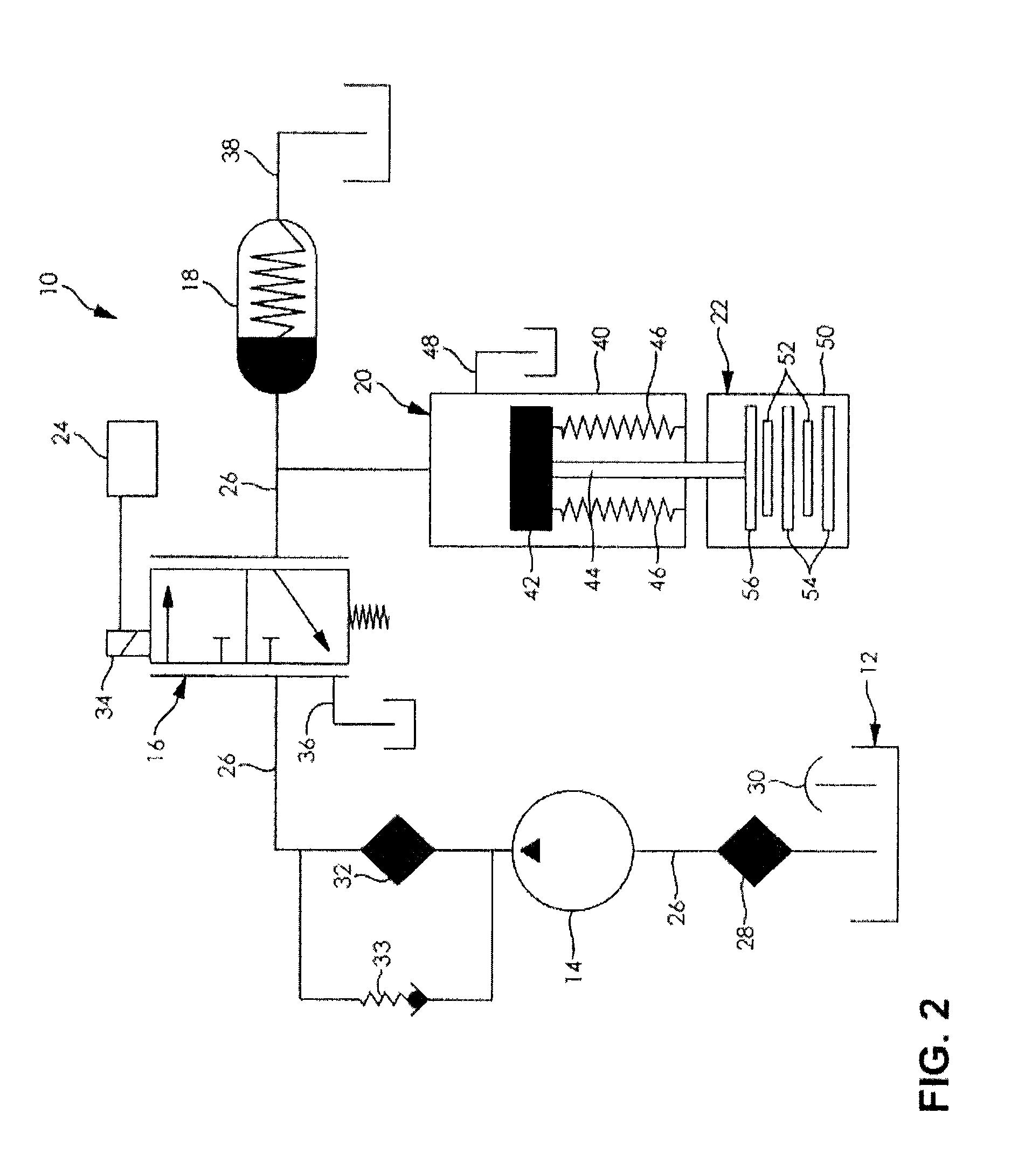
A method and a device for calibrating a wet clutch is provided. The clutch comprises a pump, a piston, a proportional valve, a controller, and a pressure sensor. The method comprises the steps of closing the clutch by sending a pressure profile with fill parameters from the controller to the proportional valve, recording a pressure signal of the hydraulic fluid, comparing the pressure profile with the pressure signal, determining whether at least one defined feature is in the pressure signal that is indicative of errors in the fill parameters, and if said feature is determined in the pressure signal, modification of the pressure profile by changing at least one of the fill parameters.

Description

RELATED APPLICATIONS[0001]The present application claims the benefit to U.S. Provisional Application No. 61 / 778,723 filed on Mar. 13, 2013, which is incorporated herein in its entirety by reference.FIELD OF THE INVENTION[0002]The present invention relates to the operation of hydraulic clutches and more specifically to an apparatus and method of learning filling parameters for wet plate clutches.BACKGROUND OF THE INVENTION[0003]In the shifting of a stepped ratio transmission, clutches are engaged and disengaged to allow for power transfer through a plurality of different power paths. Typically, when a shift is performed, one clutch is disengaged (also known as an offgoing clutch) by decreasing an oil pressure on a piston of the clutch and another clutch is engaged (also known as an oncoming clutch) by increasing a pressure on a piston of the clutch. During an overlap shift, this process happens simultaneously in a coordinated manner. In a filling phase of a shift, the piston of the o...

Claims


Application Information

Patent Timeline
Patent Type & Authority Patents(United States)
IPC IPC(8): F16D48/06
CPCF16D48/066F16D2300/18F16D2500/1026F16D2500/10412F16D2500/3024F16D2500/30415F16D2500/5014F16D2500/5018F16D2500/50236F16D2500/50245F16D2500/50251F16D2500/5102F16D2500/70217F16D2500/70406
Inventor VERSTEYHE, MARK R. J.SHARIATMADAR, KEIVAN
Owner DANA BELGIUM
Learn More