
Earthquake warning system

a technology for earthquake warning and detection, applied in direction finders, direction finders using ultrasonic/sonic/infrasonic waves, instruments, etc., can solve the problems of unnecessarily increasing computation time, affecting the accuracy of the prediction, and causing drastic differences in the respons

Inactive Publication Date: 2016-06-21
SEISMIC WARNING SYST
View PDF51 Cites 5 Cited by
  • Summary
  • Abstract
  • Description
  • Claims
  • Application Information

AI Technical Summary

Benefits of technology

The patent describes a method and system for detecting seismic events using sensors and analyzing the data to determine the intensity and location of the event. The method involves detecting the primary wave of the seismic event, determining the peak ground intensity at the sensor location, and estimating the intensity of the seismic event at a specific location. The system includes multiple sensors and a controller to process the data and issue a warning if the intensity exceeds a threshold value. The technical effects of this invention include improved detection and warning of seismic events, improved accuracy in determining the location of the event, and improved reliability of the detection system.

Problems solved by technology

This technique leads to a multiplication of uncertainties between the estimation of magnitude from P-waves and intensity from the magnitude.
In addition, time is of the essence in earthquake warnings, and this two-step estimation increases the computation time unnecessarily.
The measurement uncertainty in the estimate is typically not reported along with the estimate itself, leading to a discontinuous response behavior in which a slight change in estimated ground motion leads to a drastically different response due to a particular threshold having been exceeded.
These systems can react quickly to the arrival of a P-wave but may suffer from questionable false positive performance.
An improvement on the order of 2.4 is not generally considered possible in practice because of various system delays and hypocenter depths that were neglected in the above analysis.
In standard EWS systems, there are many sources of false positives caused by factors such as algorithm errors, electrical noise, mischief, or component failures, but the most common source of false positives is cultural noise: man-made vibrations that are difficult to distinguish from seismic events or that confuse seismic analysis algorithms.
The time spent waiting for multiple sites, however, reduces the time available for completing protective actions; time that may be of significant value in protecting lives and reducing asset loss.

Method used


Image

  • Earthquake warning system
  • Earthquake warning system
  • Earthquake warning system

Examples


Embodiment Construction

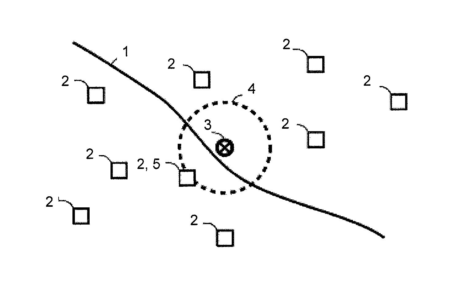
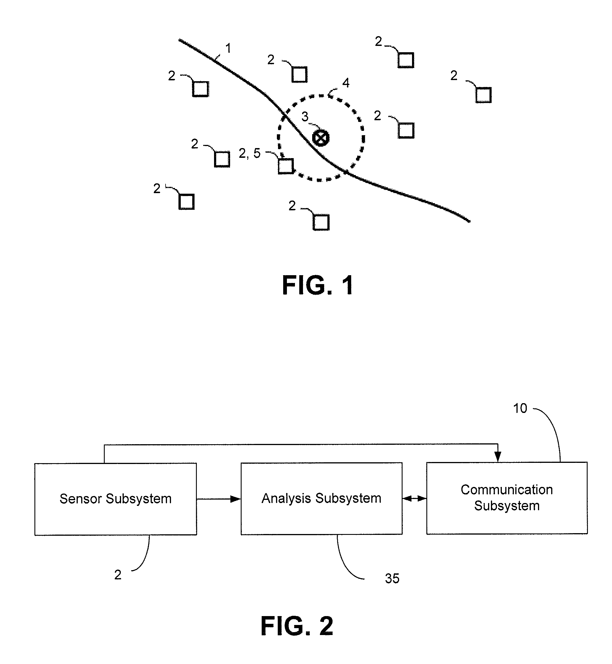
[0088]Referring to FIG. 1, a networked earthquake warning system includes geographically dispersed sites or sensor subsystems 2 placed to minimize the distance to likely earthquake centers near at least one fault 1. All sites are connected via a communications network. When an earthquake occurs at an epicenter 3, the P-wave 4 travels outwards arriving first at the closest site 5, which then sends a signal to all other affected sites 2. The warning time that the EWS can provide is better than the warning time possible with each standalone site, since the signal from the closest site 5 will arrive at the other sites 2 well before the arrival of the P-wave 4.

[0089]Referring to FIG. 2, an earthquake warning system consists of three subsystems, including a sensor subsystem 2, an analysis subsystem 35, and a communication subsystem 10.

[0090]The sensor subsystem 2 includes a controller and one or more ground motion sensors to record and report ground motion in real time. The sensor subsyst...


PUM


Abstract

A method or system for detecting a seismic event includes detecting a primary wave of a seismic event using at least one sensor at a measurement location; using at least one parameter of the detected primary wave to determine an estimated peak ground intensity at the measurement location without determining the magnitude of the seismic event; determining an epicenter of the seismic event; and estimating the intensity of the seismic event at a specified location using the determined estimated peak ground intensity and the distance of the specified location from the epicenter. The epicenter can be determined using sensors at a single location. A noise detection system can filter out detected signals that correspond to local vibrations rather than seismic events.

Description

CROSS REFERENCE TO RELATED APPLICATION[0001]This application claims priority to U.S. Provisional Application No. 61 / 424,165, filed Dec. 17, 2010, titled “Earthquake Warning System.” This application also claims priority to U.S. Provisional Application No. 61 / 424,193, filed Dec. 17, 2010, titled “Rapid, Reliable Networked Earthquake Warning System.” This application also claims priority to U.S. Provisional Application No. 61 / 424,175, filed Dec. 17, 2010, titled “Rapid, Reliable Earthquake Warning System.”[0002]All of the above referenced applications are incorporated herein by reference in their entireties.INCORPORATION BY REFERENCE[0003]All publications and patent applications mentioned in this specification are herein incorporated by reference to the same extent as if each individual publication or patent application was specifically and individually indicated to be incorporated by reference.FIELD[0004]This application relates generally to detecting and warning of earthquakes. In p...

Claims


Application Information

Patent Timeline
Patent Type & Authority Patents(United States)
IPC IPC(8): G08B21/00G01V1/00G08B21/10
CPCG01V1/008G08B21/10G01V2210/65G01V2210/72G01V2210/1232G01V1/01
Inventor PRICE, MICHAEL JOHNWURMAN, GILEAD
Owner SEISMIC WARNING SYST
Learn More