Noise reduction device and television receiver

a technology of noise reduction device and television receiver, which is applied in the direction of color television details, television system details, television systems, etc., can solve the problems of large trail behind moving images, increased noise reduction effect, and detection of input signals, so as to achieve effective noise reduction

Inactive Publication Date: 2005-09-29
KK TOSHIBA
View PDF0 Cites 31 Cited by
  • Summary
  • Abstract
  • Description
  • Claims
  • Application Information

AI Technical Summary

Benefits of technology

[0012] Accordingly, it is an object of the present invention to provide a noise reduction device and a television receiver that allow effective noise reduction without a trail behind a moving image caused by excessive control of noise reduction unit depending on signal conditions.
[0015] Preferably, in the noise reduction device, the control unit controls a level of a correction signal of the aperture correction unit and a level of the scanning velocity modulation signal of the velocity modulation unit so as to decrease the levels when the detection level of the noise detection unit is higher than a predetermined value and so as to increase the levels when the detection level of the noise detection unit is lower than a predetermined value.
[0016] According to the embodiment of the present invention, for the noise reduction unit by an arithmetic operation, a gain of a constant level at all times is set so as to suppress a trail behind a moving image. The shortage of noise reduction is compensated by a gain control of a frequency correction using a high-frequency component and a gain control of velocity modulation. As a result, the noise reduction effect can be maintained without a trail behind a moving image.
[0017] According to an embodiment of the present invention, a television receiver includes a cathode ray tube including a deflecting coil and an auxiliary deflecting coil for scanning velocity modulation, a noise reduction circuit which reduces noise by carrying out an arithmetic operation on an input video signal and one of a frame-delayed signal and a field-delayed signal of the video signal and maintains a noise reduction level to be a constant value, a noise detection circuit which detects a noise level of the video signal, an aperture correction circuit which corrects image quality using a high-frequency component extracted from the video signal as a correction signal, a velocity modulation circuit which corrects image quality by supplying a high-frequency component extracted from the video signal to the auxiliary deflecting coil as a scanning velocity modulation signal, and a control circuit which controls a level of the correction signal of the aperture correction circuit and a level of the scanning velocity modulation signal of the velocity modulation circuit in accordance with the detection level of the noise detection circuit.
[0021] According to embodiments of the present invention, for the noise reduction unit by an arithmetic operation, a gain of a constant level at all times is set so as to suppress a trail behind a moving image. The shortage of noise reduction is compensated by a gain control of a frequency correction using a high-frequency component and a gain control of velocity modulation. As a result, the noise reduction effect can be maintained without a trail behind a moving image caused by the noise reduction unit depending on signal conditions.

Problems solved by technology

Also, this method can increase the noise reduction effect when the gain of the AGC is large.
However, since a moving picture component in the signal is also considered as noise, the moving picture component is viewed as an image having a trail behind it when the gain is increased.
In this case, the noise level of an input signal is detected.
However, when the gain of the AGC is large, a trail behind a moving image becomes large.
In this case, the gain control using a result of the noise detection excessively controls a noise reduction unit.
In particular, a noise reduction unit using an arithmetic operation produces a trail behind a moving image, thus considerably deteriorating the visual image.

Method used


Image

  • Noise reduction device and television receiver
  • Noise reduction device and television receiver
  • Noise reduction device and television receiver

Examples


Embodiment Construction

[0028] Embodiments of the present invention will be described below with reference to the accompanying drawings.

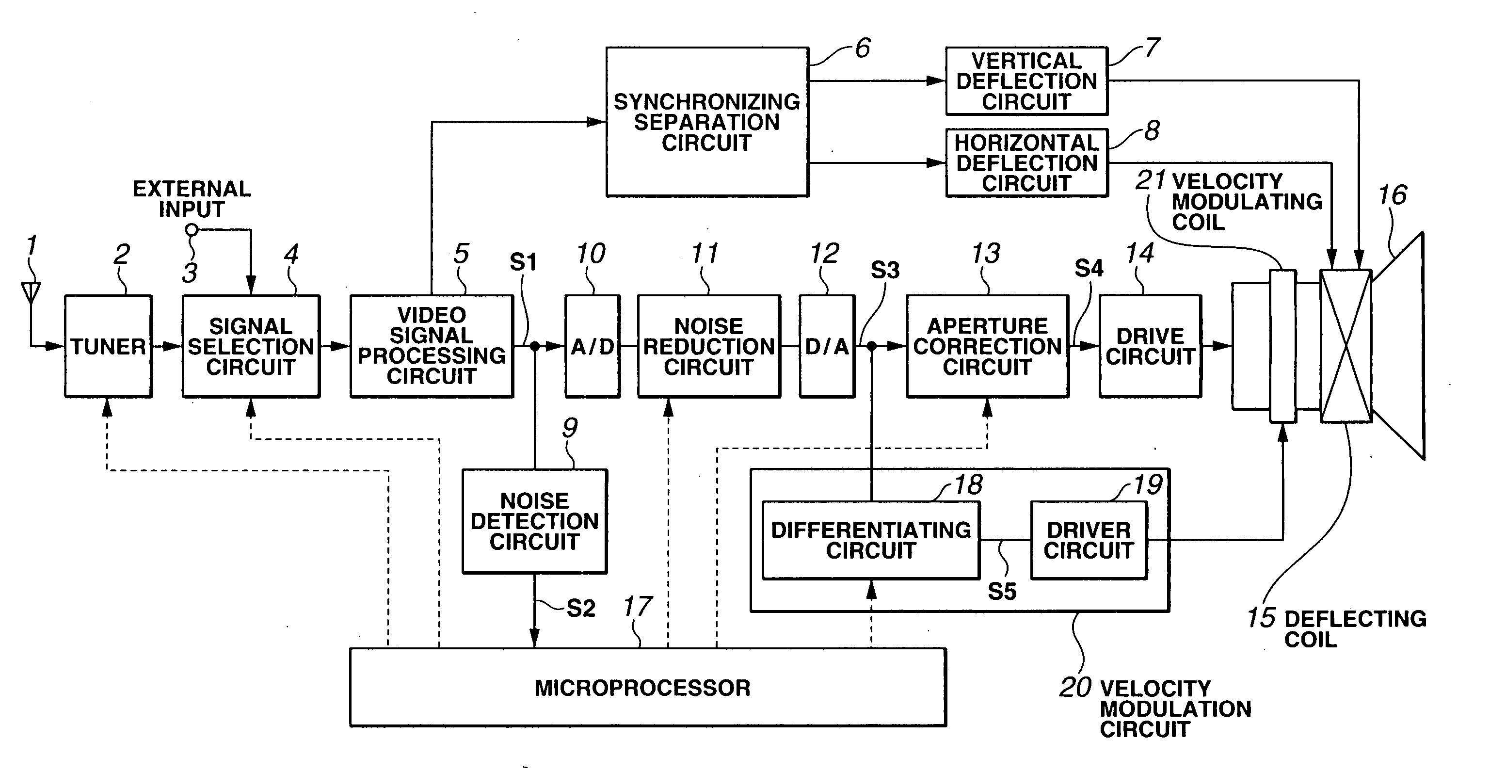
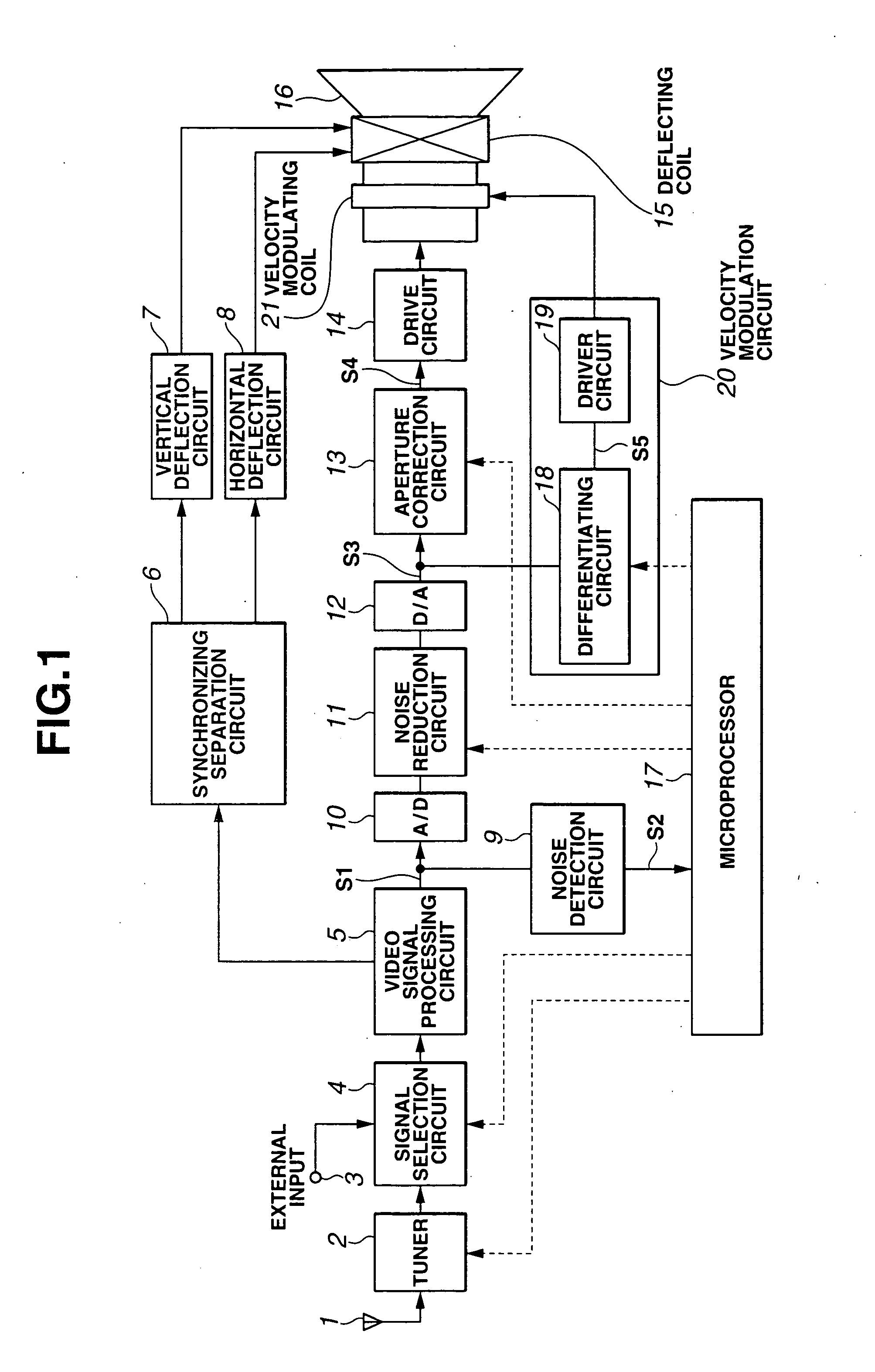
[0029]FIG. 1 is a block diagram of a noise reduction device according to a first embodiment of the present invention. In the first embodiment, a noise reduction device of a television receiver will be described.

[0030] As shown in FIG. 1, the noise reduction device of the television receiver includes an antenna 1, a tuner 2, an external input terminal 3, a signal selection circuit 4, a video signal processing circuit 5, a synchronizing separation circuit 6, a vertical deflection circuit 7, a horizontal deflection circuit 8, a noise detection circuit 9, an A / D converter 10, a noise reduction circuit 11, a D / A converter 12, an aperture correction circuit 13, a drive circuit 14, a deflecting coil 15, a cathode ray tube 16, a microprocessor 17 functioning as a control unit, a velocity modulation circuit 20 composed of a differentiating circuit 18 and a drive circuit 19, and a...


PUM


Abstract

A noise reduction circuit performs noise reduction by an arithmetic operation on an input video signal and its one-frame delayed video signal. At that time, a noise reduction level is always maintained at a constant value that suppresses a trail behind a moving image. An aperture correction circuit performs image-quality correction by using a high frequency component extracted from the video signal as a correction signal. When a detection level of a noise detection circuit exceeds a predetermined value, the level of the correction signal is controlled to decrease. A velocity modulation circuit supplies the high frequency component extracted from the video signal to an auxiliary deflecting coil of a cathode ray tube as a scanning velocity modulation signal so as to perform image-quality correction. When a detection level of the noise detection circuit exceeds a predetermined value, the level of the scanning velocity modulation signal is controlled to decrease.

Description

CROSS-REFERENCE TO RELATED APPLICATIONS [0001] This application is based upon and claims the benefit of priority from the prior Japanese Patent Application No. 2004-93503 filed on Mar. 26, 2004; the entire contents of which are incorporated herein by reference. BACKGROUND OF THE INVENTION [0002] 1. Field of the Invention [0003] The present invention relates to a noise reduction device of a video signal in video equipment, such as a television receiver, and a television receiver. [0004] 2. Description of the Related Art [0005] In general, in a noise reduction function of a television receiver, a noise level of an input video signal is detected and the noise reduction ratio is controlled in accordance with the detected noise level. [0006] To detect the noise, a predetermined portion of the input video signal in a vertical blanking interval is retrieved by a gate circuit. The amplitude value of that portion of the signal is detected by a detection circuit and is output as a detection v...

Claims


Application Information

Patent Timeline
Patent Type & Authority Applications(United States)
IPC IPC(8): H04N3/32H04N5/208H04N5/21H04N5/213
CPCH04N3/32H04N5/21H04N5/208
Inventor SUZUKI, TAKASHI
Owner KK TOSHIBA
Why Eureka
Try Eureka