

Switch with overload release structure
- Summary
- Abstract
- Description
- Claims
- Application Information
AI Technical Summary
Benefits of technology
Problems solved by technology
Method used
Image

Examples
Embodiment Construction
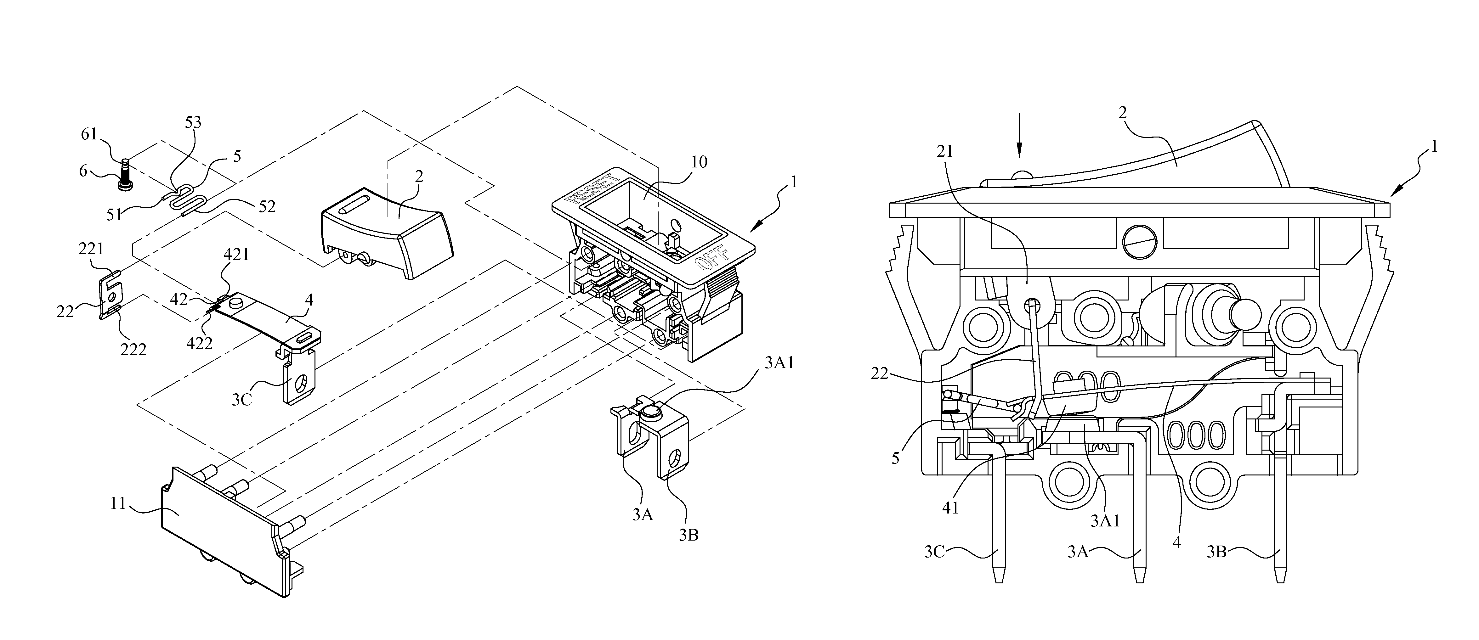
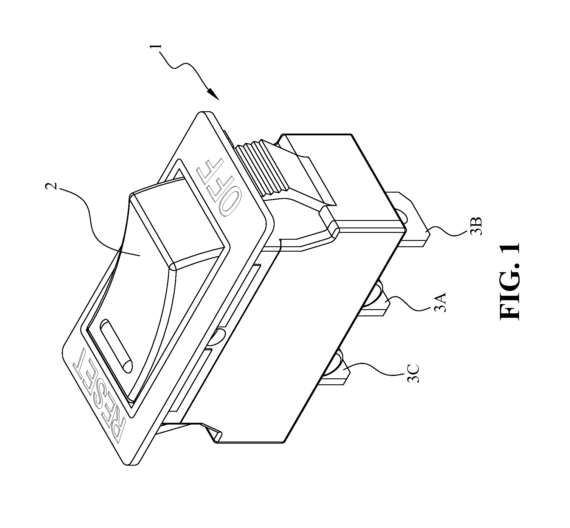
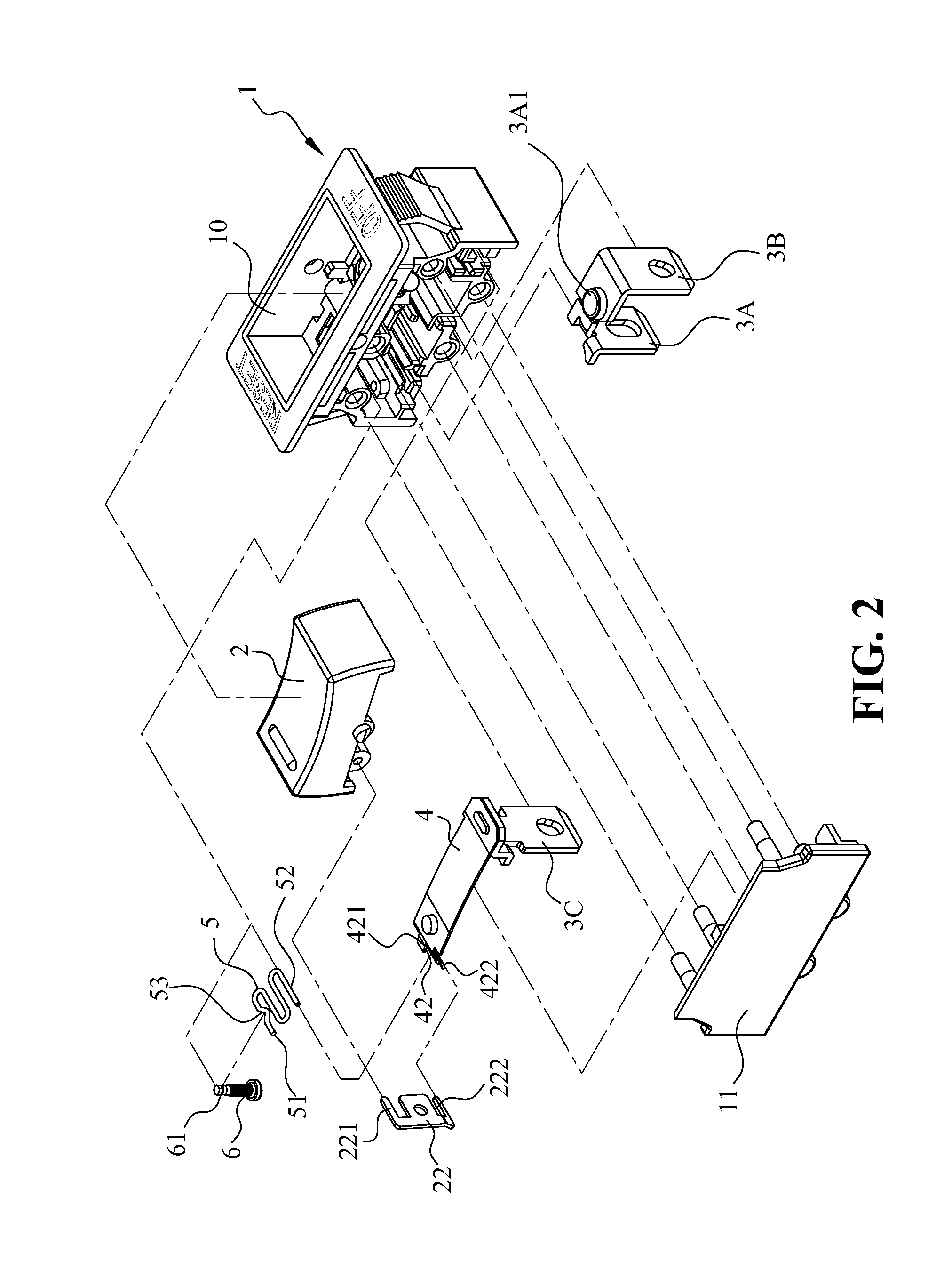
[0024]Referring to FIGS. 1 to 3, wherein FIG. 1 shows a perspective view of a switch with an overload release structure of the present invention; FIG. 2 shows an exploded view of the switch of the present invention; and FIG. 3 shows a cross-sectional view of the switch of the present invention in a switch-off position or when an overload current flows therethrough. As illustrated, the switch with an overload release structure of the present invention includes a switch casing 1, a button 2, an alloy plate 4 and an elastic member 5. The switch casing 1 defines an interior chamber with a bottom, and includes conductive first and second prongs 3A, 3B that are disposed within the interior chamber and that have lower prong portions exposed to an exterior of the interior chamber via the bottom for electrically coupling to a hot wire and a neutral wire of an electrical power source. The conductive first and second prongs 3A, 3B further have upper prong portions located within the interior c...
PUM
 Abstract
Description
Claims
Application Information