
Decision based re-processing framework for radar technology

a reprocessing framework and radar technology, applied in the field of signal processing, can solve the problems of reducing the amount of data needed to be transferred directly, limited computational resources available for analysis, etc., and achieve the effect of less computational resources, efficient and adaptable use of available computational resources, and effective scanning

Active Publication Date: 2020-09-01
SAAB AB
View PDF2 Cites 0 Cited by
  • Summary
  • Abstract
  • Description
  • Claims
  • Application Information

AI Technical Summary

Benefits of technology

The patent is about a method for analyzing radar signals in a scenario-based manner. By focusing computational resources on relevant data within the radar detection scenario, the method improves efficiency and flexibility. The method also involves storing the signal data on a data storage device, which allows for later retrieval and analysis of the data. This approach, known as context-based analysis, helps to identify relevant data and use appropriate algorithms for analysis. The method can also use indications, such as signal-to-noise ratio, model parameter estimation, or feature estimation, to select relevant data. Overall, the method provides an efficient and adaptable way to analyze radar signals and is useful in various applications such as detection, identification, and tracking of objects.

Problems solved by technology

Radar detection is field typically involving high load streaming of radar signal data with only limited computational resources available to analyse the streaming radar signal data.
Further, it potentially reduces the amount of data needed to be transferred directly between the first computational resource and the aggregating module of the corresponding system.

Method used


Image

  • Decision based re-processing framework for radar technology
  • Decision based re-processing framework for radar technology
  • Decision based re-processing framework for radar technology

Examples


Embodiment Construction

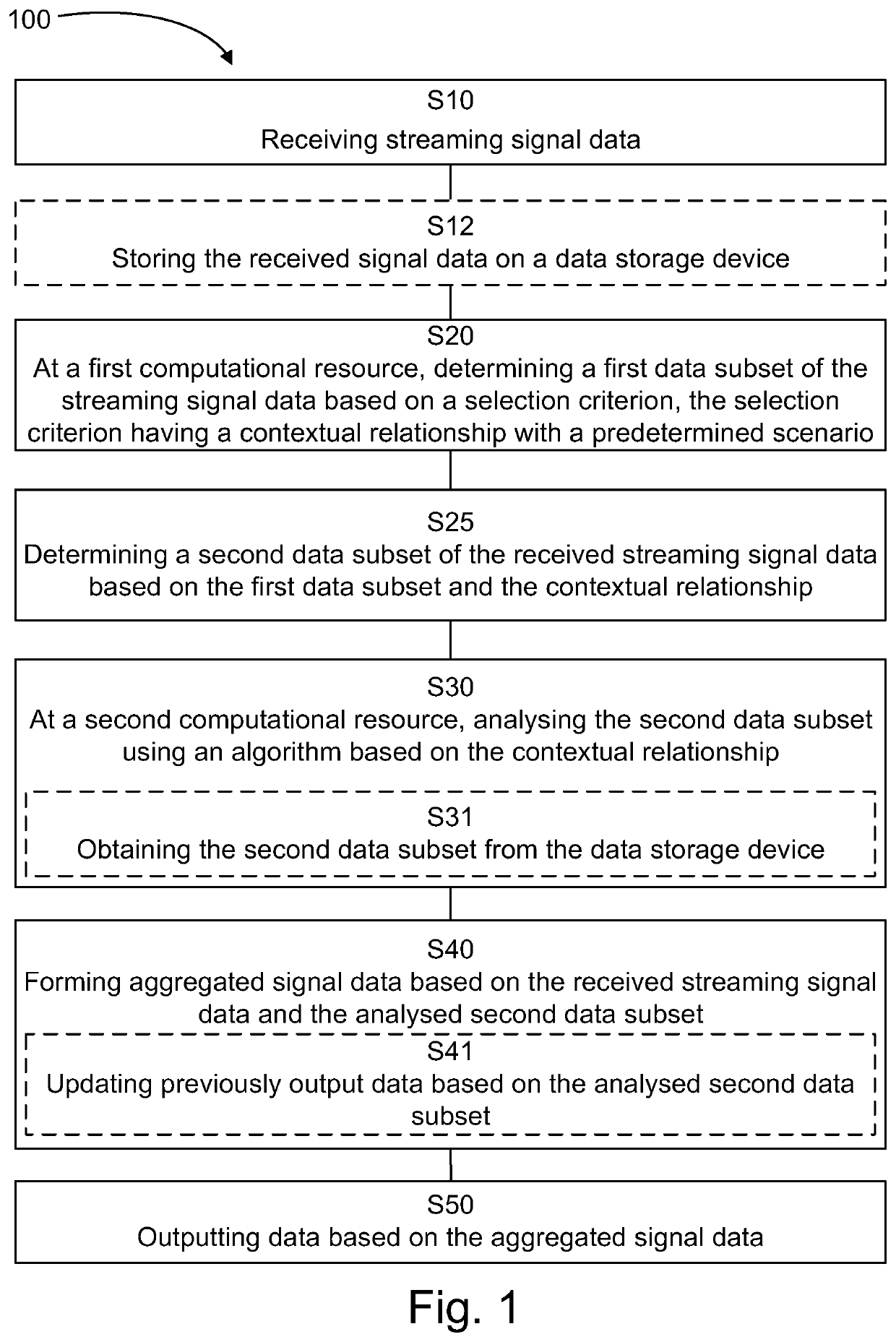
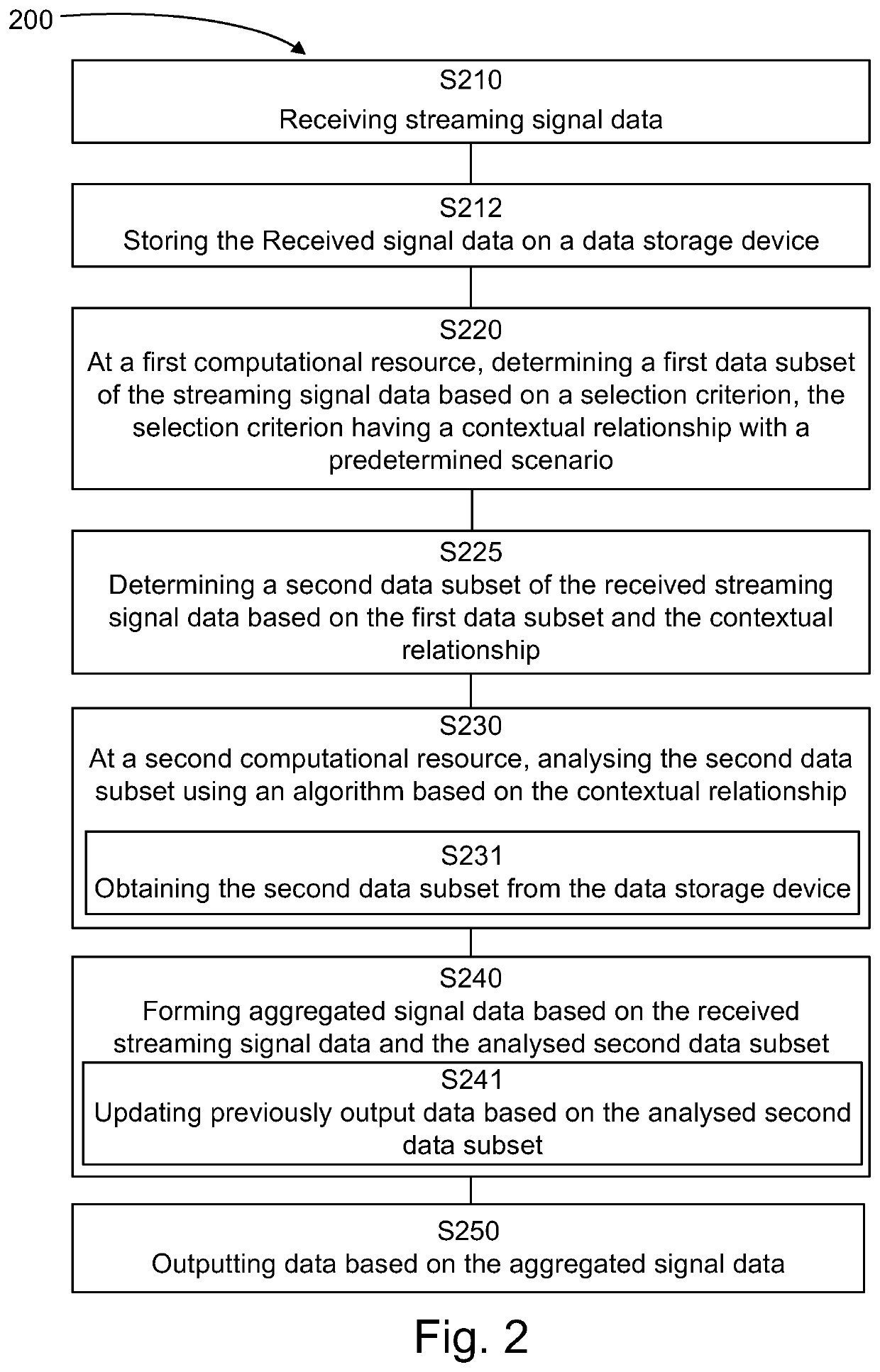
[0017]FIG. 1 is a flow chart illustrating method steps of a method 100 for signal processing resource allocation, e.g. radar signal processing resource allocation. The method is based on the realisation that the available computational resources may be partitioned into a first computational resource dedicated to scan the streaming signal data, e.g. streaming radar signal data, using an algorithm suitable for high signal throughput processing, and a second computational resource dedicated to process a subset of interest identified by the first computational resource using an algorithm suitable for high performance signal processing. In other words, the first computational resource provides a preliminary result, which may trigger, possibly at some future point in time, a need for further analysis by the second computational resource. In addition to enabling the use of high performance algorithms to process relevant subsets of the signal data stream, the partitioning of the computation...


PUM


Abstract

The present disclosure relates to a method for signal processing resource allocation. The method comprises receiving (S10) streaming signal data. The method further comprises, at a first computational resource, determining (S20) a first data subset of the streaming signal data based on a selection criterion, the selection criterion having a contextual relationship with a predetermined scenario. The method also comprises determining (S25) a second data subset of the received streaming signal data based on the first data subset and the contextual relationship. The method additionally comprises, at a second computational resource, analysing (S30) the second data subset using an algorithm based on the contextual relationship. The method further comprises forming (S40) aggregated signal data based on the received streaming signal data and the analysed second data subset. The method yet further comprises outputting (S50) data based on the aggregated signal data. The present disclosure also relates to corresponding systems and computer programs.

Description

CROSS REFERENCE TO RELATED APPLICATIONS[0001]This application is a National Stage Application, filed under 35 U.S.C. 371, of International Application No. PCT / SE2017 / 050278, filed Mar. 22, 2017, the contents of which are hereby incorporated by reference in their entirety.BACKGROUNDRelated Field[0002]The present disclosure relates to signal processing. More specifically, the present disclosure relates to improved signal processing performance for real time analysis of high signal loads and limited signal processing resources.Description of Related Art[0003]During real time use of radar technology, vast amounts of signal data typically need to be processed. However, the computational resources needed to perform the desired high performance signal processing functions are typically expensive, and often require dedicated environments and considerable power during operational use. It is therefore common that the computational resources available to perform signal processing are limited a...

Claims


Application Information

Patent Timeline
IPC IPC(8): G01S13/58G06F17/18
CPCG06F17/18G01S13/584G01S7/41
Inventor ERIKSSON, STEFAN
Owner SAAB AB
Learn More