Core sampling apparatus and container transfer apparatus

a sampling apparatus and container technology, applied in the field of core sampling apparatus and container transfer apparatus, can solve the problems of ball valves that may stop at the edge, not sealed perfectly, semi-closed or insufficiently closed,

Inactive Publication Date: 2016-06-28
JAPAN AGENCY FOR MARINE-EARTH SCIENCE AND TECHNOLOGY
View PDF9 Cites 3 Cited by
  • Summary
  • Abstract
  • Description
  • Claims
  • Application Information

AI Technical Summary

Benefits of technology

[0014]Depending on the drilling state, core sampling from a stratum which is apt to collapse may be desired. However, in the case of the stratum that is apt to collapse, drilling mud water may be circulated at a high pressure after the core drilling to prevent collapse.
[0028]In the embodiment of the present invention, it is possible to maintain the state in which the ball valve is closed and maintain the internal pressure of the apparatus by providing the locking mechanism for locking the sealed state after the ball valve sealed by the first sealing member.

Problems solved by technology

Because of this, the ball valve may stop at the edge, and is not sealed perfectly.
That is, it becomes semi-closed or insufficiently closed.
Thus, when the pressurized water is injected after the ball valve is opened, the pressurized water leaks from the ball valve, the internal pressure is rarely to increase enough to raise the pressure tightness.
Therefore, the ball valve is easily moved due to vibration caused during the recovery (the rise), and the pressure tightness thereof cannot be maintained.
Accordingly, the hydraulic head pressure and the internal pressure become equal, and the pressure in the autoclave becomes the pressure at the stable point in time, and thus unevenness occurs in pressure maintenance at the hole bottom.

Method used


Image

  • Core sampling apparatus and container transfer apparatus
  • Core sampling apparatus and container transfer apparatus
  • Core sampling apparatus and container transfer apparatus

Examples


Embodiment Construction

[0047]Hereinafter, embodiments of a core sampling apparatus and a container transfer apparatus according to the present invention will be described in detail with reference to the drawings. Meanwhile, in the description of the drawings, identical elements have assigned identical symbols, and duplicate description thereof is omitted. Further, the dimensional ratios of the drawings do not necessarily accord with what is described.

[0048](Configuration of Core Barrel)

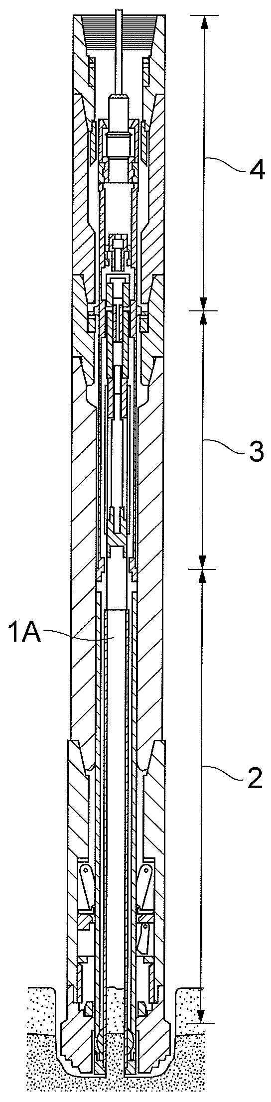
[0049]FIG. 1 shows a core barrel 1 (a core sampling apparatus) according to the present embodiment. As shown in FIG. 1, the core barrel 1 includes an autoclave 2 for sampling a core, a pressure control part 3 for maintaining an internal pressure of the core barrel 1, and a pull-up unit 4 for pulling up the autoclave 2, in order from a lower side at the core drilling condition. The autoclave 2 includes a container (a core liner) which is movably disposed in an axial direction in a barrel part (an inner barrel) 1A forming the...


PUM


Abstract

Provided is a core sampling apparatus which maintains the internal pressure after the core drilling.The core sampling apparatus includes a barrel part, a container which is movably disposed in the barrel part and maintains the sampled core, a ball valve to prevent a fluid from inflowing and outflowing between an inside and an outside of the barrel part in a closed state thereof, a first seal member which seals a space between the barrel part and the ball valve, a second seal member which seals a space between the container and the barrel part, a locking mechanism which locks a state in which the ball valve is sealed by the first seal member, and an inflowing mechanism configured to inflow the fluid only in a direction to an internal space of the closed barrel part by the first seal member and the second seal member.

Description

RELATED APPLICATIONS[0001]The present application is based on, and claims priority from, Japanese Application Number 2013-053301, filed Mar. 15, 2013, the disclosure of which is hereby incorporated by reference herein in its entirety.BACKGROUND OF THE INVENTION[0002]1. Field of the Invention[0003]The present invention relates to a core sampling apparatus that samples a core while maintaining an internal pressure of the apparatus and a container transfer apparatus that transfers a container in the core sampling apparatus to a predetermined apparatus.[0004]2. Related Background Art[0005]In scientific drilling, etc., although many researchers and engineers have been making developments for the purpose of obtaining a stratum column-shaped sample (a core) with a pressure in the stratum maintained for many years, they are still far from completion. Recently, in oil field drilling, there has been a special coring system called a “pressure temperature core sampler (PTCS)”, which has been de...

Claims


Application Information

Patent Timeline
Patent Type & Authority Patents(United States)
IPC IPC(8): E21B25/00E21B25/08
CPCE21B25/08E21B25/005E21B25/00
Inventor MIZUGUCHI, YASUHIKO
Owner JAPAN AGENCY FOR MARINE-EARTH SCIENCE AND TECHNOLOGY
Why Eureka
Try Eureka