Pressure cap for cooling system of vehicle

a technology for cooling systems and pressure caps, which is applied in the direction of sealing, functional valve types, machines/engines, etc., can solve the problems of complex structure of pressure caps and increase manufacturing costs, and achieve the effect of simple structur

Active Publication Date: 2020-04-14
HYUNDAI MOTOR CO LTD +1
View PDF11 Cites 1 Cited by
  • Summary
  • Abstract
  • Description
  • Claims
  • Application Information

AI Technical Summary

Benefits of technology

[0012]Various aspects of the present invention are directed to providing a pressure cap for a cooling system of a vehicle that has a simple structure and can maintain internal pressure within a predetermined range.
[0026]In the pressure cap for a cooling system of a vehicle constituted as described above in accordance with various aspects of the present invention, since structure of the internal to the pressure cap is simplified by eliminating a negative pressure spring, possibility of failure of components is reduced and hence reliability of operation of the pressure cap is secured and quality control is facilitated.
[0027]Furthermore, since the structure is simple, manufacturing cost can be reduced.
[0028]Moreover, since the number of springs used for pressure control is reduced, elastic force of the spring can be easily adjusted.

Problems solved by technology

However, in the pressure cap 110 for a cooling system of a vehicle having the structure as described above, there is a problem in that since pressure is regulated by use of both the positive pressure valve 113 and the negative pressure valve 114, structure of the pressure cap is complicated and thus manufacturing cost is increased.

Method used


Image

  • Pressure cap for cooling system of vehicle
  • Pressure cap for cooling system of vehicle
  • Pressure cap for cooling system of vehicle

Examples


Embodiment Construction

[0041]Reference will now be made in detail to various embodiments of the present invention(s), examples of which are illustrated in the accompanying drawings and described below. While the invention(s) will be described in conjunction with exemplary embodiments, it will be understood that the present description is not intended to limit the invention(s) to those exemplary embodiments. On the contrary, the invention(s) is / are intended to cover not only the exemplary embodiments, but also various alternatives, modifications, equivalents and other embodiments, which may be included within the spirit and scope of the invention as defined by the appended claims.

[0042]Hereinafter, a pressure cap for a cooling system of a vehicle according to an exemplary embodiment of the present invention is described more specifically with reference to the accompanying drawings.

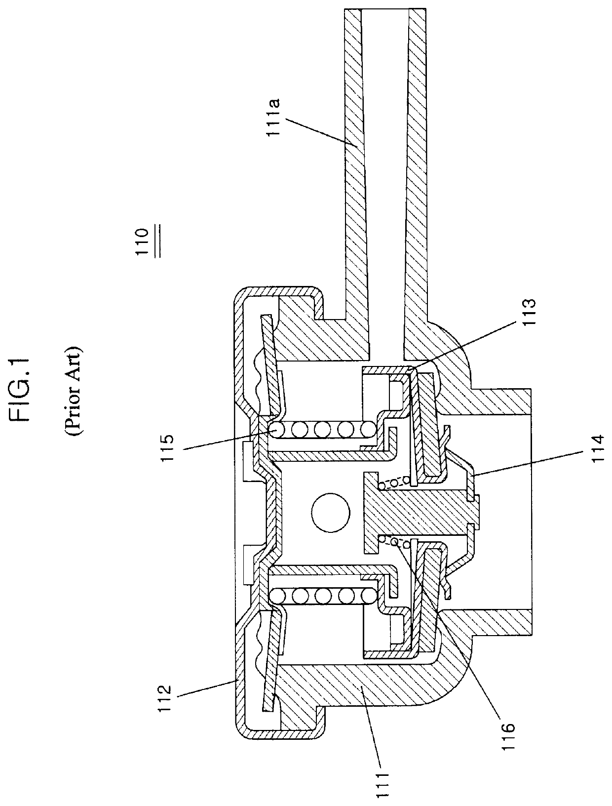
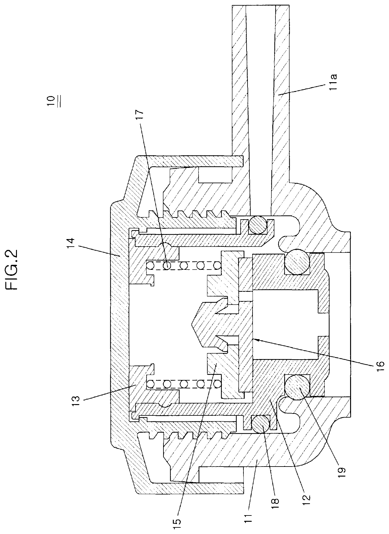
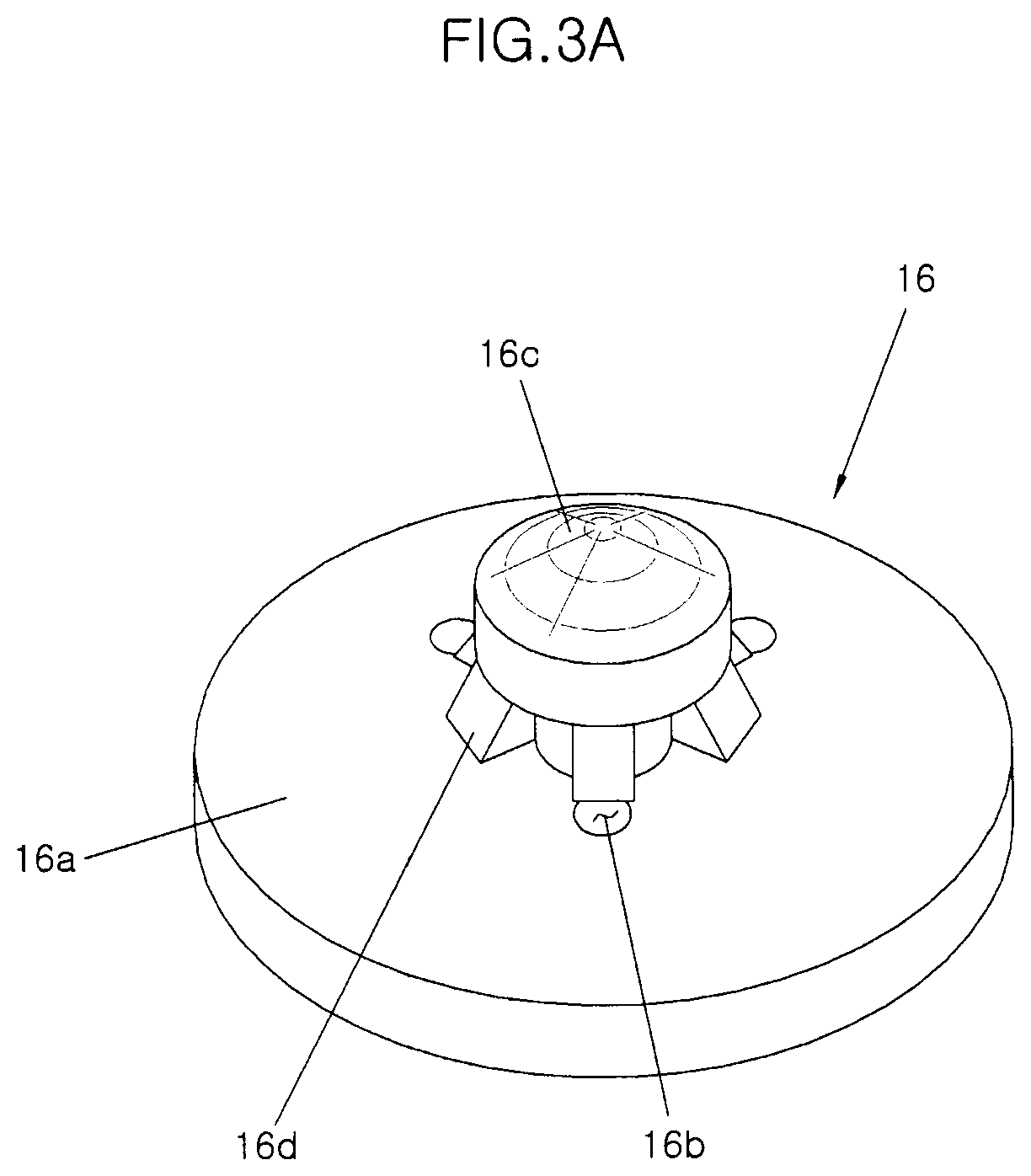
[0043]A pressure cap 10 for a cooling system of a vehicle according to an exemplary embodiment of the present invention include...


PUM


Abstract

A pressure cap for a cooling system of a vehicle may include a reservoir fill port which is mounted at an upper portion of a reservoir in which cooling water is stored in a cooling system of the vehicle; an external cap for closing an upper end portion of the reservoir fill port; a pressure valve disposed in the reservoir fill port to allow the inside and the outside of the reservoir fill portion to fluidically-communicate with each other; a valve seal provided to allow the air to flow from the outside into the internal to the cooling system by being deformed when pressure in the internal to the cooling system is lower than a predetermined pressure; and a positive pressure spring elastically supporting the pressure valve such that the pressure valve closes the internal to the reservoir fill port.

Description

CROSS-REFERENCE TO RELATED APPLICATIONS[0001]The present application claims priority to Korean Patent Application No. 10-2016-0169648, filed on Dec. 13, 2016, the entire contents of which is incorporated herein for all purposes by this reference.BACKGROUND OF THE INVENTIONField of the Invention[0002]The present invention relates to a pressure cap for a cooling system of a vehicle, which is mounted at an upper portion of a reservoir in which cooling water is stored or a radiator through which cooling water flows into a cooling system of a vehicle, and more particularly, to a pressure cap for a cooling system of a vehicle that has a simple structure and can adjust internal pressure without degrading performance.Description of Related Art[0003]Vehicles are provided with a radiator for cooling heat generated by operation of an engine by radiating the heat generated from the engine to the outside and a cooling system for circulating cooling water from the engine to the radiator.[0004]Fur...

Claims


Application Information

Patent Timeline
Patent Type & Authority Patents(United States)
IPC IPC(8): B65D51/16F01P11/02F16K24/00F16K17/196B65D51/24
CPCF16K17/196F01P11/0238F16K24/00F01P2011/0228F01P2011/0233F01P11/0214F01P11/00F01P2011/0242F01P11/0209F01P11/029Y10S277/944
Inventor CHA, YONG-WOONGYUN, JOONG-SUCHO, WAN-JE
Owner HYUNDAI MOTOR CO LTD
Why Eureka
Try Eureka