Turbine engine fan

a turbine engine and fan technology, applied in the direction of liquid fuel engine components, non-positive displacement fluid engines, pump components, etc., can solve the problems of limiting the angular movement of the blades, premature wear of the stops, and low rotation speed that does not allow enough centrifugation of the blades, etc., to achieve simple, economical and effective

Active Publication Date: 2016-06-28
SN DETUDE & DE CONSTR DE MOTEURS DAVIATION S N E C M A
View PDF20 Cites 2 Cited by
  • Summary
  • Abstract
  • Description
  • Claims
  • Application Information

AI Technical Summary

Benefits of technology

[0009]The aim of the invention is in particular to afford a simple, economical and effective solution to these various problems.

Problems solved by technology

The flanks of each lug form stops for retaining the blades and thus limit their angular movement.
This low rotation speed does not allow sufficiently great centrifugation of the blades for locking thereof in position in the slots.
These repeated contacts cause rubbing between the flanks of the lugs and the blades, leading to premature wear on the stops, which requires more frequent repairs to the stops.
However, the lugs of the disc thus repaired have a lower fatigue strength than that of the lugs of a new disc.
In addition, these depositions of material have limited impact resistance and may progressively disintegrate over time.
Finally, this operation cannot be performed under the wing and requires dismantling and repair in a maintenance workshop, which leads to lengthy and expensive immobilisation times and requires the use of expensive and complex tooling.

Method used


Image

  • Turbine engine fan
  • Turbine engine fan
  • Turbine engine fan

Examples


Embodiment Construction

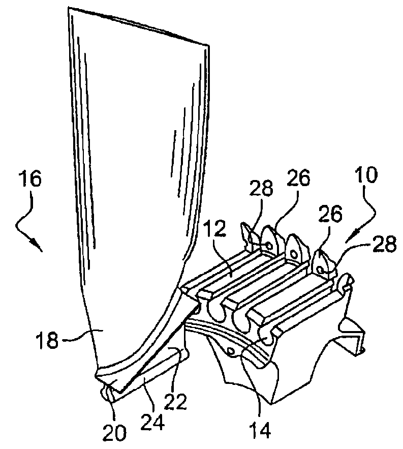
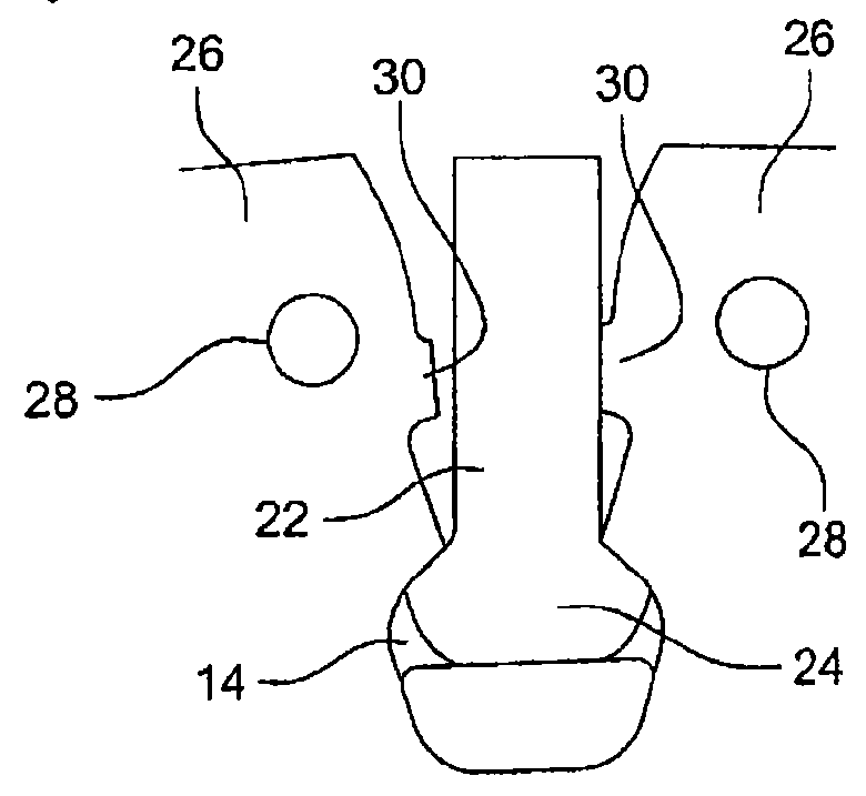
[0026]Reference is made first of all to FIG. 1, which shows schematically part of a turbine engine fan disc 10 comprising, at its external periphery, longitudinal ribs 12 delimiting between them slots 14 for the axial mounting and radial holding of blades 16. Each blade 16 comprises a vane 18, a platform 20 formed at the base of the vane and delimiting internally the annular stream for the air flow entering the turbine engine. A zone 22 known as the “prop” connects the platform 20 and the vane 18 to a blade root 24.

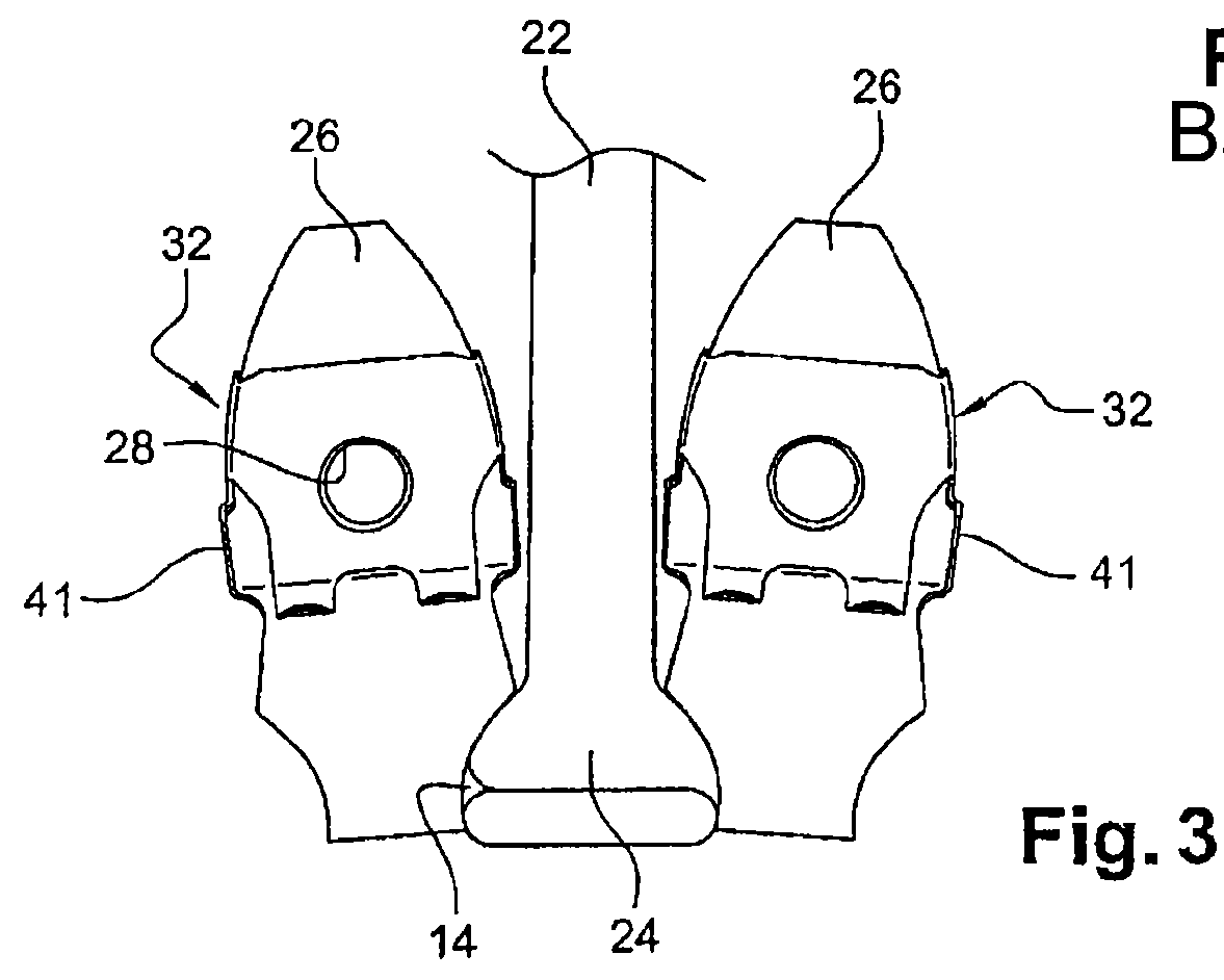
[0027]Each rib 12 of the fan disc 10 comprises a radial lug 26 formed at its downstream end. These lugs 26 each comprise an axial orifice 28 intended to be aligned with a corresponding orifice formed in an annular flange of a low-pressure compressor rotor arranged downstream (see FIG. 5). Fixing screws are inserted in the orifices 28 in the lugs 26 of the disc 10 and in the orifices in the annular flange of the compressor rotor.

[0028]Each radial lug 26 comprises lateral f...


PUM


Abstract

A turbine engine air blower including a rotor disk that includes, on an outer periphery thereof, longitudinal ribs, each including a radial lug for attaching the disk onto a downstream compressor rotor. The flanks of the lugs form abutments for holding vanes that are mounted onto the disk. A mechanism protecting flanks of the lugs is circumferentially inserted between the lugs and the vanes.

Description

BACKGROUND OF THE INVENTION[0001]1. Field of the Invention[0002]The present invention concerns a fan of a turbine engine, such as an aircraft jet engine or turboprop engine.[0003]2. Description of the Related Art[0004]In a known fashion, a turbine engine fan comprises a rotor disc having at its external periphery a plurality of longitudinal ribs delimiting between them slots for the axial mounting and radial retention of blade roots. The downstream end of each rib comprises a radial lug comprising an orifice for a screw or bolt to pass for fixing the fan disc onto an upstream flange of a low-pressure compressor arranged downstream of the fan. The low-pressure compressor is thus driven in rotation with the rotor of the fan by a turbine shaft.[0005]The flanks of each lug form stops for retaining the blades and thus limit their angular movement. In the event of loss of a blade, the blade disconnected from the disc impacts an adjacent blade, which tilts angularly and comes into abutment...

Claims


Application Information

Patent Timeline
Patent Type & Authority Patents(United States)
IPC IPC(8): F01D5/30F04D29/32
CPCF01D5/3007F01D5/3092F04D29/322F05C2201/0466
Inventor DELAPIERRE, MICHAELJEAN-LOUIS REGHEZZA, PATRICK
Owner SN DETUDE & DE CONSTR DE MOTEURS DAVIATION S N E C M A
Why Eureka
Try Eureka