Beam-based nonlinear spring

a nonlinear spring and beam technology, applied in the direction of shock absorbers, machines/engines, instruments, etc., to achieve the effect of effective behavior, maximize power dissipation, and maximize power

Inactive Publication Date: 2016-07-05
MASSACHUSETTS INST OF TECH
View PDF17 Cites 4 Cited by
  • Summary
  • Abstract
  • Description
  • Claims
  • Application Information

AI Technical Summary

Benefits of technology

[0022]One embodiment considers a cantilever beam that oscillates between two contact surfaces with carefully selected curvature. The resulting nonlinear spring has a negligible linearized component, the order of its nonlinearity does not remain constant but increases as the amplitude gets larger, and the spring achieves a theoretically infinite force for a finite displacement. The last property is of crucial importance since it allows the device to act as a typical spring with polynomial nonlinearity for moderate vibration amplitudes and to effectively behave as a vibro-impact spring for larger amplitudes.
[0023]The nonlinear oscillator can be a one-degree-of-freedom oscillator or a component in a multi-degree-of-freedom oscillator. Nonlinear oscillators are useful in targeted energy transfer applications such as ambient energy harvesting because they are adaptive and robust to the stochastic, multi-frequency signals of ambient vibrations. Furthermore, nonlinear oscillators maximize the power dissipated when they have large amounts of damping, whereas linear oscillators tend to maximize the power dissipated for low amounts of damping. For energy harvester applications, an energy harvester with a large amount of damping tends to be more robust to the presence of parasitic damping (less power decay) than a harvester with low parasitic damping.
[0024]The nonlinear spring may also be used to make a stiffening load cell. A load cell that uses the present invention has a force resolution that is high for small forces and lower for large forces, which allows a high force accuracy over a large force range. Also, the stiffening behavior and geometry prevent it from breaking for forces well beyond its designed range.
[0025]The hardening nonlinearity of the springs in the load cell allow the load cell to deflect a large distance for small forces and incrementally smaller distances for larger forces. For very large forces, the flexible members of the load cell effectively do not bend further because they are already in contact with the surfaces along the full flexible member length. The surfaces are significantly stiffer than the flexible members and can be designed to negligibly deform themselves in all desired applications.
[0026]In one aspect, the nonlinear spring according to the invention includes two opposed curved surfaces curving away from one another and a flexible cantilever member disposed between the two opposed curved surfaces. A mass is attached to a free end of the cantilever member wherein the flexible cantilever member wraps around one of the curved surfaces as the cantilever member deflects to form a nonlinear spring. In a preferred embodiment of this aspect of the invention the curved surfaces have a variable radius of curvature along their length. In one embodiment, the curved surfaces have an infinite radius of curvature at their root and radius of curvature decreases with distance from the root. The opposed curved surfaces may include teeth to reduce mechanical damping.

Problems solved by technology

Furthermore, nonlinear oscillators maximize the power dissipated when they have large amounts of damping, whereas linear oscillators tend to maximize the power dissipated for low amounts of damping.

Method used


Image

  • Beam-based nonlinear spring
  • Beam-based nonlinear spring
  • Beam-based nonlinear spring

Examples


Embodiment Construction

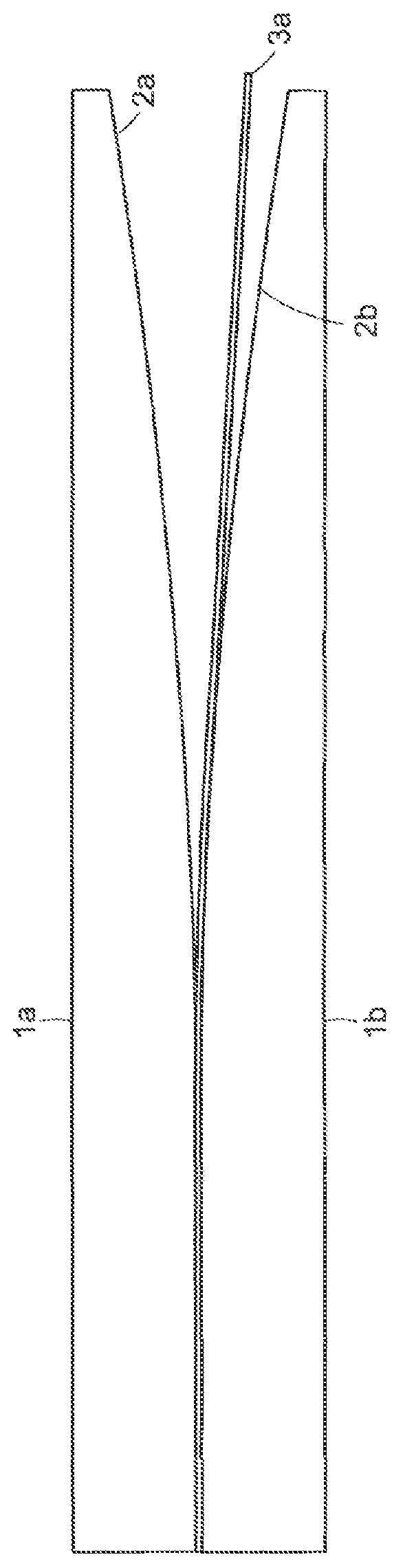
[0047]FIG. 1 is a side view of an embodiment of the invention disclosed herein. The embodiment in FIG. 1 has a depth into the page. In this embodiment, a beam 3a is clamped between top surface la and bottom surface 1b. In this embodiment, the beam 3a is a cantilever. In other embodiments, the right end of beam 3a may have another boundary condition or be attached to another object. In this embodiment, curves 2a and 2b are flat at their leftmost ends so that they clamp beam 3a. To the right of the flat segment, Curves 2a and 2b have decreasing radius of curvature along their lengths in the right direction.

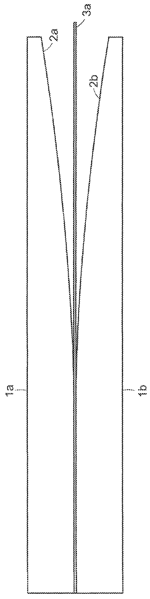
[0048]FIG. 2 shows that cantilever 3a wraps around the bottom surface curve 2b when a downward force is applied to the tip of cantilever 3a. In this embodiment, for increasing forces, an increasing segment of the cantilever contacts the surface, starting at the root. If an upward force is applied to the cantilever tip 3a, then the cantilever would wrap around the top surface curve 2...


PUM

PropertyMeasurementUnit
forceaaaaaaaaaa
forceaaaaaaaaaa
weightaaaaaaaaaa

Abstract

Nonlinear spring. In one embodiment, the spring includes two opposed curved surfaces curving away from one another. A flexible cantilever member is disposed between the two opposed curved surfaces and a mass is attached to a free end of the cantilever member wherein the flexible cantilever member wraps around one of the curved surfaces as the cantilever member deflects to form a nonlinear spring. Energy harvesting devices and a load cell are also disclosed.

Description

[0001]This application claims priority to provisional application Ser. No. 61 / 941,593 filed on Feb. 19, 2014, the contents of which are incorporated herein by reference in their entirety.[0002]This invention was made with Government support under Contract No. N65540-10-C-003 awarded by the Department of Defense—Department of the Navy. The Government has certain rights in the invention.BACKGROUND OF THE INVENTION[0003]This relates to a stiffening nonlinear spring formed by a flexible cantilever member wrapping around a curved surface as it deflects.[0004]Several technological processes such as energy harvesting from ambient vibrations, shock absorption from external loads, and passive control or suppression of mechanical instabilities involve targeted energy transfer from one component of a structure to another. In particular, energy harvesting is the process of using ambient energy sources to generate useful forms of energy such as electricity. The energy in these ambient sources is...

Claims


Application Information

Patent Timeline
Patent Type & Authority Patents(United States)
IPC IPC(8): F16F1/22F03G1/00F03G1/02G01L1/00H02K7/18F03G1/10H02K35/02G01L1/04F03G7/08
CPCF16F1/22F03G1/00F03G1/02F03G1/10F03G7/08G01L1/00G01L1/044H02K7/1876H02K35/02F16F15/035F16F7/104H10N30/306G01B7/16G01B11/16
Inventor KLUGER, JOCELYN MAXINESLOCUM, ALEXANDER HENRYSAPSIS, THEMISTOKLIS PANAGIOTIS
Owner MASSACHUSETTS INST OF TECH
Why Eureka
Try Eureka