
Corrosion protection of steel in concrete

a technology of concrete and corrosion protection, applied in the field of electrochemical protection of steel in reinforced concrete, can solve the problems of inability of air cathode in anode assembly to deliver the necessary protective current, and the inability of air cathode in the anode assembly to work, so as to prolong the shelf life of the modifier

Active Publication Date: 2012-09-25
GLASS GARETH KEVIN +2
View PDF23 Cites 4 Cited by
  • Summary
  • Abstract
  • Description
  • Claims
  • Application Information

AI Technical Summary

Benefits of technology

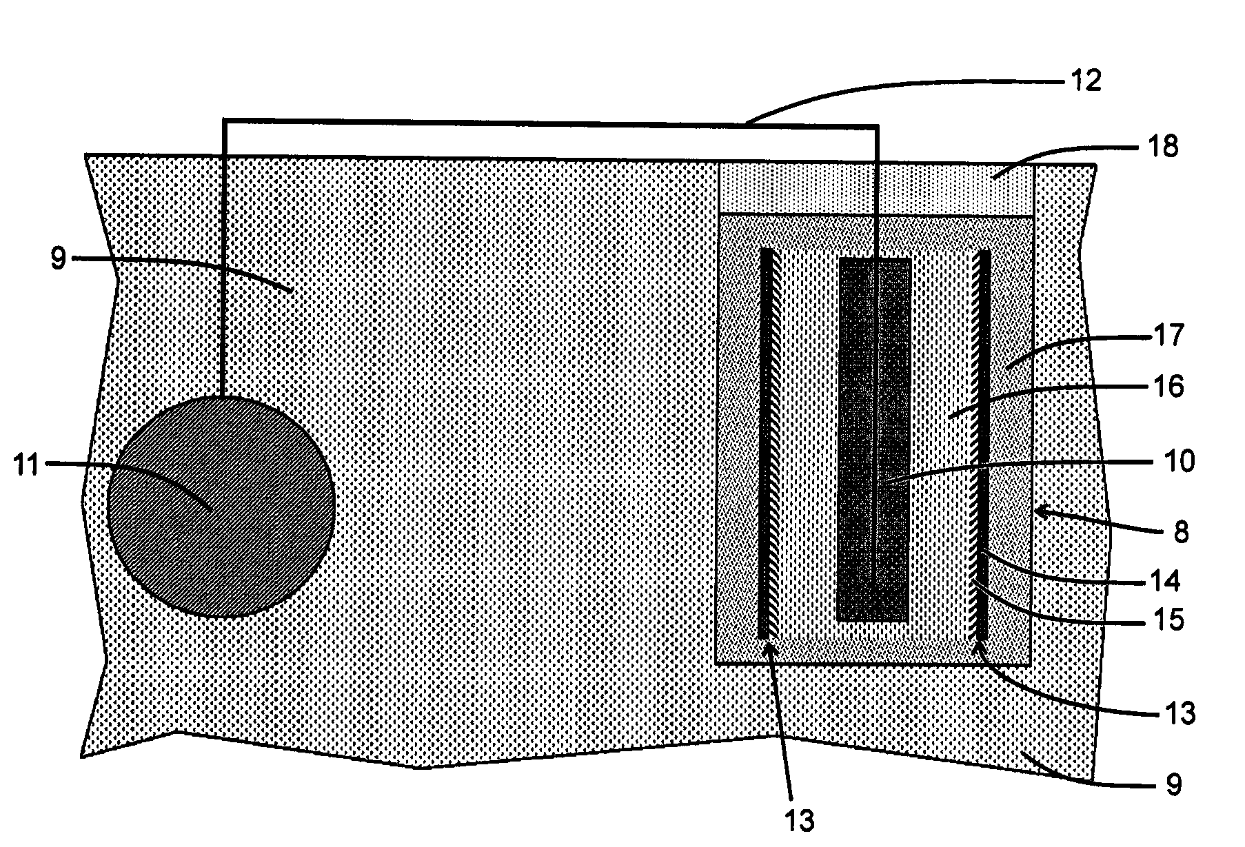
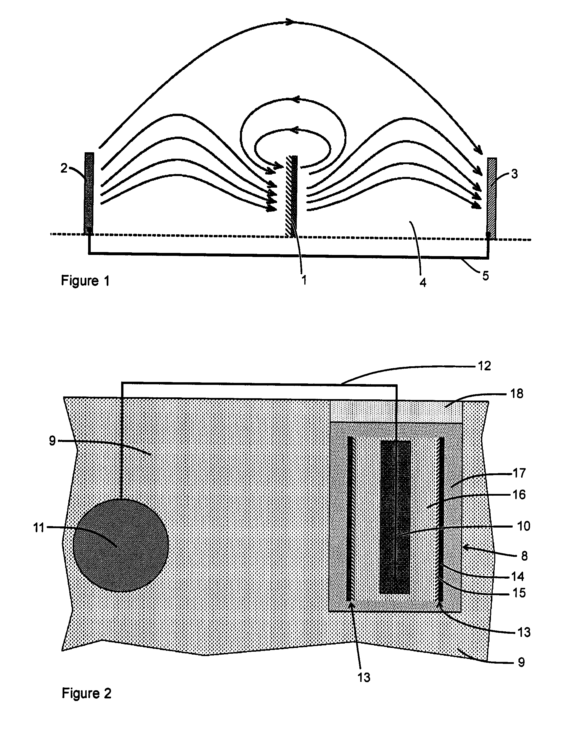
[0019]The electric field modifier contains at least one anode electrode, electronically connected by an electron conducting conductor, to at least one cathode electrode and the anode and the cathode face away from each other. The oxidation reaction on the anode (anode reaction) and the reduction reaction on the cathode (cathode reaction) can occur without any external driving potential. One type of electric field modifier is an element comprising a first side or face that is an anode supporting an oxidation reaction that is in electrical contact with a second side or face that is a cathode supporting a reduction reaction so that the anode and the cathode face away from each other (i.e., the anode and the cathode both face in substantially different directions). A natural potential difference is generated by the oxidation and the reduction reactions on the anode and the cathode, respectively, that tries to drive a current through the modifier. If an electrolyte connects the anode of the modifier to its cathode, the circuit will be complete and a current will flow from the anode to the cathode. Electrochemical reactions consume the reducing and the oxidizing agents at the anode and cathode, respectively (i.e., the reductants are oxidized and oxidants are consumed at the anode and cathode, respectively). It is preferable that these reactions should be restricted prior to use to enhance the shelf life of the modifier. This may be achieved by keeping the modifier in a dry environment in order to limit the quantity of electrolyte at the anode and the cathode, and / or by preventing the electrolyte at the anode from making contact with the electrolyte at the cathode. The modifier is located in the electric field between the sacrificial anode and the steel. The modifier increases the current flowing through a path that intersects the modifier when the cathode of the modifier faces the sacrificial anode and the anode of the modifier faces away from the sacrificial anode. In this arrangement, the modifier may also be used to increase the total current delivered by the sacrificial anode. The modifier effectively behaves as a current pump that pumps electric current through the modifier.

Problems solved by technology

In an environment, like soil and water, where cathodic protection is achieved by cathodically polarizing the steel, an air cathode will not work because the steel to be protected represents an air cathode with a very large surface area relative to the air cathode that might be assembled within an anode assembly and, therefore, the air cathode in the anode assembly will not have the capacity to deliver the necessary protective current.

Method used


Image

  • Corrosion protection of steel in concrete
  • Corrosion protection of steel in concrete
  • Corrosion protection of steel in concrete

Examples


example 1

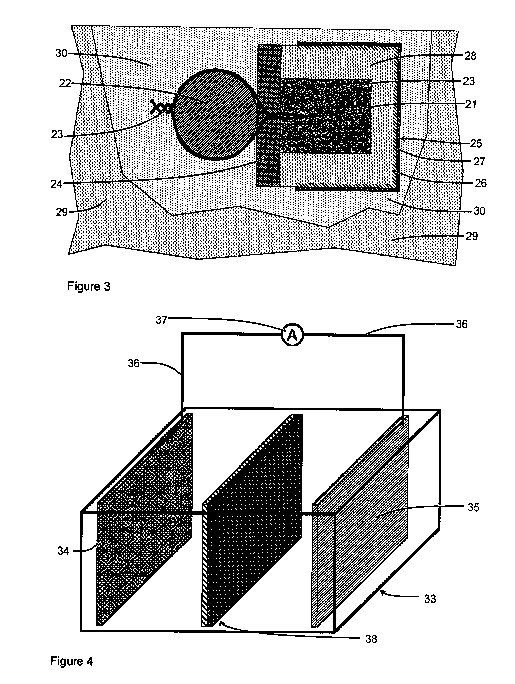
[0061]An electric field modifier was constructed using a zinc casing of a standard zinc chloride D size cell (also referred to as a zinc-carbon battery with the International Electrotechnical Commission classification of R20). A sheet of zinc was cut from the casing and flattened and sanded to clean any deposit(s) from the zinc. It measured approximately 55×100 mm. One side of the zinc sheet was coated with two coats of an electrically conductive silver paint, of the type used to make electrical connections on circuit boards. The sheet was then baked at 240° C. for 15 minutes to remove the coating solvent. Carbon was then rubbed onto the silvered surface to produce a loose thin grey coating. Any coating on the reverse side of the zinc sheet was removed using a 220 grit sandpaper to leave a clean, bright zinc surface. The silver and carbon surface is designed to act as an air electrode (i.e., the cathode) and facilitate reduction of the oxidizing agent, e.g., oxygen, while the zinc s...

example 2

[0069]Two electric field modifiers of approximately 55×50 mm in size were constructed using the same zinc sheet, as described in Example 1. One side of each zinc sheet was first coated with two coats of silver paint and then baked, as described in Example 1. Thus one side of each sheet was zinc and the other side was a conductive silver coating. The silver coated surface was then coated with a carbon rich paint. Two make the carbon paint, the carbon bar from the center of a zinc-carbon battery was sanded down to produce a fine carbon powder. The power was mixed with a drop of clear outdoor varnish and approximately 10 times as much varnish solvent thinner. A carbon to binder ratio, in the dry paint film of somewhat greater than 10:1, was targeted. The painted zinc sheet was then baked further to remove the solvent. The conductivity of the painted surface was checked using a resistance meter with two probes which were lightly pressed onto the carbon coated surface. The resistivity wa...

example 3

[0075]FIG. 8 shows the test arrangement for Example 3. According to this embodiment, two cement mortar blocks 41, each 270 mm long by 175 mm wide by 110 mm high, were cast using damp sand, Portland Cement® and water in the weight ratio 4:1:0.8. The mortar was of a relatively poor quality and some bleed water formed on top of the casting. During the casting process, a steel cathode 42, with a surface area of 0.12 m2, was positioned within the outer edge of each mortar block. The steel cathode 42 was formed from two 300 mm by 100 mm steel shims that were cut and folded to form a set of 20 mm wide by 90 mm long steel strips connected by a 10 mm by 300 mm strip, to allow both sides of the steel to receive current during the testing process. A segment of the cut and folded steel cathode 42 is shown in FIG. 9. An electric cable 43 was connected to the steel cathode 42 and extended beyond the cement mortar 41 to enable electrical connections to be made to the steel cathode 42. A hole 44, 4...


PUM

PropertyMeasurementUnit
diameteraaaaaaaaaa
voltageaaaaaaaaaa
current densityaaaaaaaaaa

Abstract

An electric field modifier for boosting a current output of a sacrificial anode to enhance its protective effect and direct the current output to improve current distribution in galvanic protection of steel in a concrete element exposed to air is disclosed. A cavity is formed in a concrete element and a combination comprising a sacrificial anode, an electric field modifier and an ionically conductive filler are embedded therein. The sacrificial anode is connected to the steel. The modifier comprises an element with an anode side, supporting an oxidation reaction, in electrical contact with a cathode side, supporting a reduction reaction. The cathode of the modifier faces the sacrificial anode and is separated therefrom by a filler which contains an electrolyte that connects the sacrificial anode to the cathode of the modifier. The anode of the modifier faces away from the sacrificial anode. Preferably, the reduction reaction, on the cathode of the modifier, comprises reduction of oxygen from the air.

Description

FIELD OF THE INVENTION[0001]The present invention relates to electrochemical protection of steel in reinforced concrete construction using sacrificial anodes and, in particular, to the use of distributed discrete sacrificial anode assemblies in arresting steel corrosion in corrosion damaged concrete elements which are exposed to the air.BACKGROUND OF THE INVENTION[0002]As is well known in the art, above ground steel reinforced concrete structures suffer from corrosion induced damage mainly as the result of carbonation or chloride contamination of the concrete. As the steel reinforcement corrodes, it produces byproducts that occupy a larger volume than the steel from which the byproducts are derived. As a result, expansion occurs in the concrete around reinforcing steel bars. This causes cracking and delamination of the concrete cover over the steel. Typical repairs involve removing this patch of corrosion damaged concrete from the reinforced concrete structures. It is good practice ...

Claims


Application Information

Patent Timeline
Patent Type & Authority Patents(United States)
IPC IPC(8): C23F13/14C23F13/12C23F13/16C23F13/10C23F13/08
CPCC23F13/06C23F13/02C23F13/08C23F13/10C23F13/16C23F13/20C23F2201/02
Inventor GLASS, GARETH KEVINROBERTS, ADRIAN CHARLESDAVISON, NIGEL
Owner GLASS GARETH KEVIN
Learn More