Charger with replaceable plug

a plug and replaceable technology, applied in the field of chargers, can solve the problems of increasing cost, bringing electric shock, logistics in the passive situation, etc., and achieve the effects of enhancing stable connection, precise and stably, and convenient us

Inactive Publication Date: 2016-07-05
DONGGUAN YUHUA ELECTRONICS TECH
View PDF2 Cites 0 Cited by
  • Summary
  • Abstract
  • Description
  • Claims
  • Application Information

AI Technical Summary

Benefits of technology

[0006]The primary object of the present invention is to provide a charger with a replaceable plug to overcome the shortcomings of the prior art. The charger is simple in structure and convenient to use, and has a good effect.
[0011]Accordingly, the present invention comprises an existing charger having a plug combined with a removable plug, so that the charger can be used more conveniently. The removable plug and the charger body are connected through the grooves and positioning raised ribs to enhance stable connection between the removable plug and the charger body. Furthermore, the grooves have positioning grooves along the lengthwise direction, and the positioning raised ribs have guide ribs thereon corresponding to the positioning grooves. Through the positioning hole and the resilient positioning buckle, the removable plug and the charger body are connected and positioned more precisely and stably. The positioning raised ribs of the removable plug comprises the conductive metal elastic pieces therein corresponding to the conductive pins of the folding plug to complete the circuit connection of the removable plug and the charger. In this way, the charger can use a desired plug according to different sockets, so it is flexible, simple and safe for use.

Problems solved by technology

If the orders for chargers are uncertain or the demands for certification are unknown, this will cause the logistics in the passive situation.
In addition, the cost is increased.
Without safety protection, it may bring an electric shock.

Method used


Image

  • Charger with replaceable plug
  • Charger with replaceable plug
  • Charger with replaceable plug

Examples


Embodiment Construction

[0016]Embodiments of the present invention will now be described, by way of example only, with reference to the accompanying drawings.

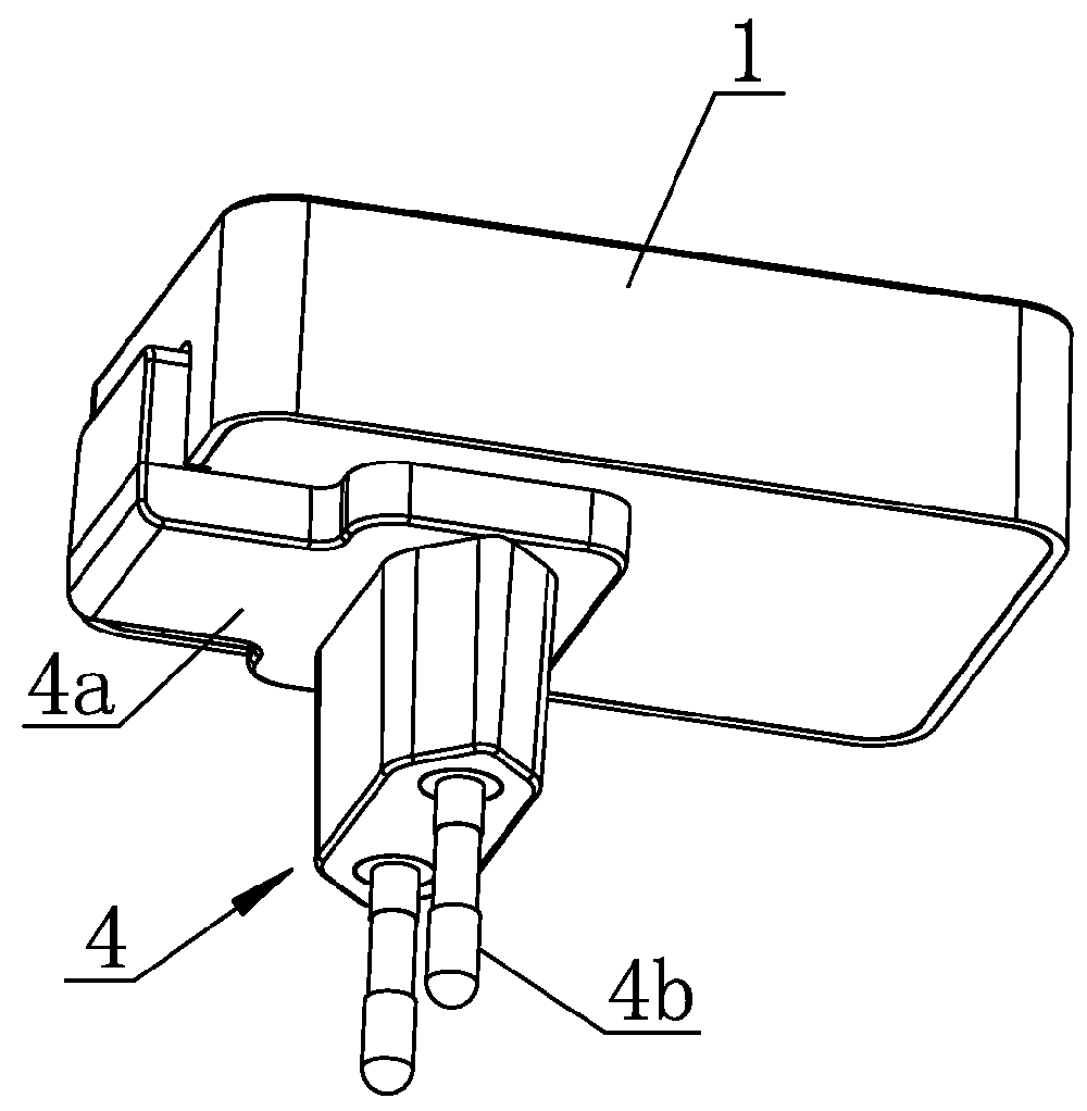
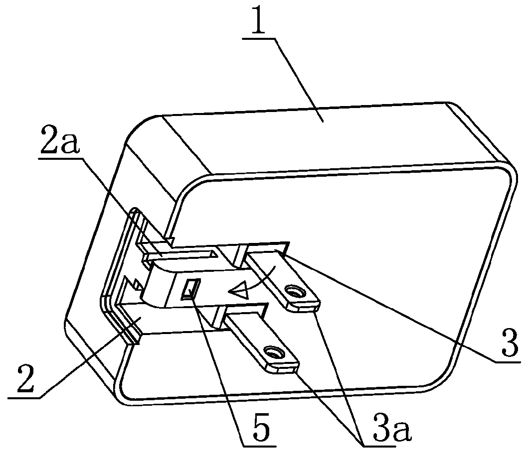
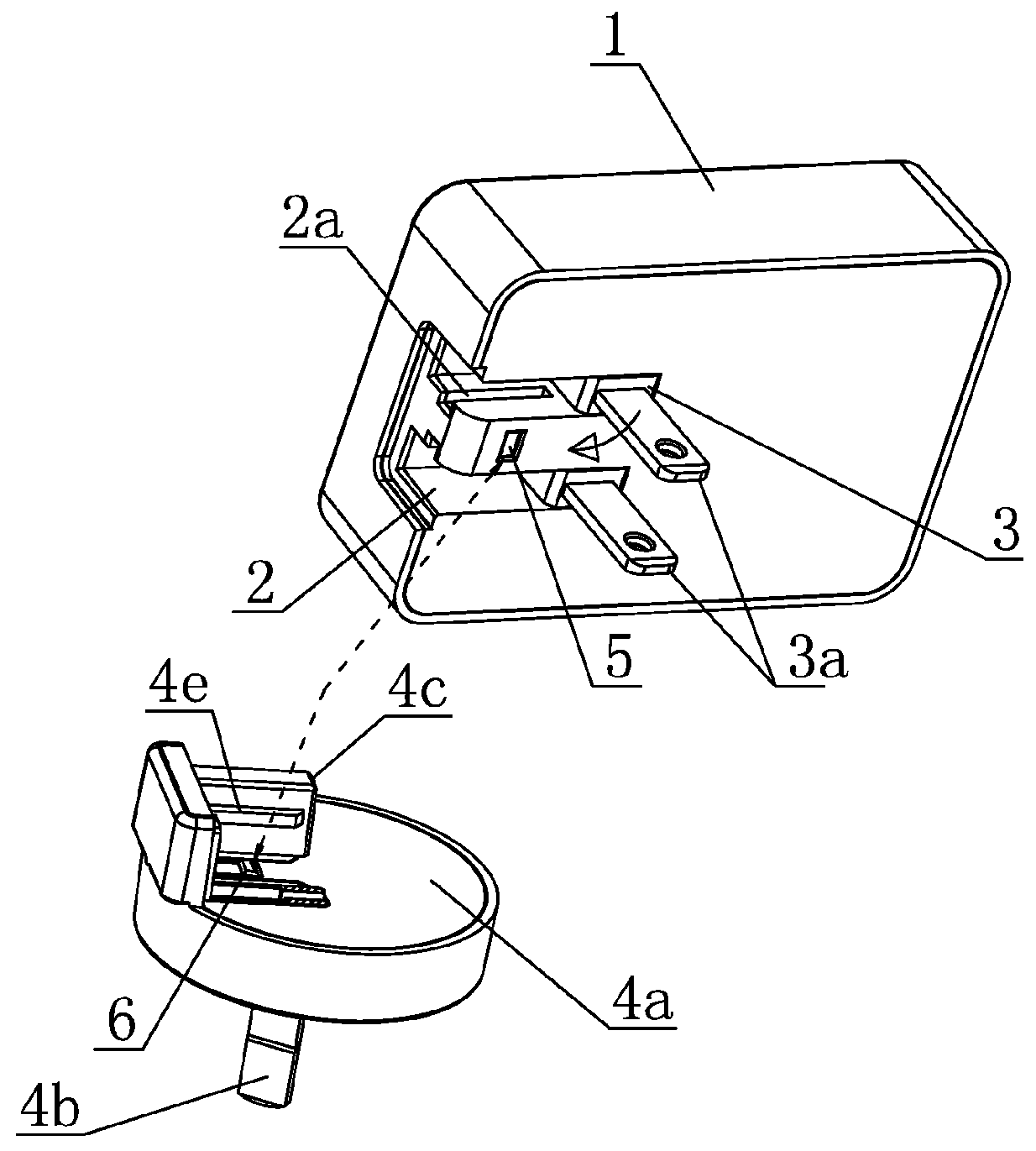
[0017]FIG. 1 to FIG. 6 shows a charger with a replaceable plug according to a first embodiment of the present invention. The present invention comprises a charger body 1. The charger body 1 has a groove 2 at an end portion of a side of the charger body 1. A folding plug 3 is hinged in the groove 2. In this embodiment, the folding plug 3 is a US-type folding plug. Of course, the folding plug 3 may be other types, not limited. A European-type removable plug 4 is also plugged in the groove 2. The removable plug 4 comprises a support 4a, conductive pins 4b and positioning raised ribs 4c disposed on the support 4a, and conductive metal elastic pieces 4d electrically connected with the conductive pins 4b. The positioning raised ribs 4c have connecting holes 4f at ends thereof facing conductive pins 3a of the folding plug 3 for insertion of the conductive pi...


PUM


Abstract

A charger with a replaceable plug includes a charger body; a groove is provided on an end portion of a lateral surface of the charger body, and a folding plug is hinged in the groove. A removable plug is also plugged in the groove, and the removable plug is formed of a support, conductive pins and positioning raised ribs disposed on the support, and conductive metal elastic pieces connected with the conductive pins; an end face of the positioning raised ribs, facing the conductive pins of the folding plug is provided with connecting holes matching the conductive pins, and the conductive metal elastic pieces are arranged in the connecting holes. When the positioning raised ribs are plugged into the groove, the conductive metal elastic pieces are tightly connected with the conductive pins of the folding plug. The present invention is simple in structure and convenient to use.

Description

BACKGROUND OF THE INVENTION[0001]1. Field of the Invention[0002]The present invention relates to a charger, and more particularly to a charger with a replaceable plug.[0003]2. Description of the Prior Art[0004]A charger must comply with the demand of safety because it relates to strong current. The specification for plugs in each country is different, and the demand for certification is also different. Therefore, to development a universal charger for different countries, different AC plugs, and different demands of certification becomes very important.[0005]The existing chargers are a one-piece formed structure, namely, the plug and the charger body are integrally formed by injection molding. The plug and the charger body cannot be detached from each other. Thus, chargers sold to different countries must be designed according to different demands. If the orders for chargers are uncertain or the demands for certification are unknown, this will cause the logistics in the passive situ...

Claims


Application Information

Patent Timeline
Patent Type & Authority Patents(United States)
IPC IPC(8): H02J7/02H02J7/00H01R31/06
CPCH02J7/0042H01R31/065H02J7/0052H02J7/00
Inventor ZOU, QING
Owner DONGGUAN YUHUA ELECTRONICS TECH
Why Eureka
Try Eureka