
Golf club shaft for wood club

a golf club and wood technology, applied in the field of wood golf club shafts, can solve the problems of reducing impulse, affecting the performance of golf clubs, and affecting the performance of golf clubs, and achieve the effect of uniform strength distribution and lightening weigh

Active Publication Date: 2016-07-12
MITSUBISHI CHEM CORP
View PDF20 Cites 6 Cited by
  • Summary
  • Abstract
  • Description
  • Claims
  • Application Information

AI Technical Summary

Benefits of technology

The solution achieves a uniform strength distribution, allowing for further weight reduction while ensuring the shaft meets the necessary strength reference values at all points, thereby eliminating surplus weight and enhancing the lightest weight class for various stiffness types.

Problems solved by technology

However, an inertia moment of the club is increased only by simply making the shaft long, so that players may feel the club “heavy” at the time of swing.
There is a technique for lightening weight of the club head as a means to solve this problem, but when the weight of the club head is lightened, an impulse is reduced at the time of an impact of the club head with a ball, and thus it is not expected that the carry distance is largely increased.
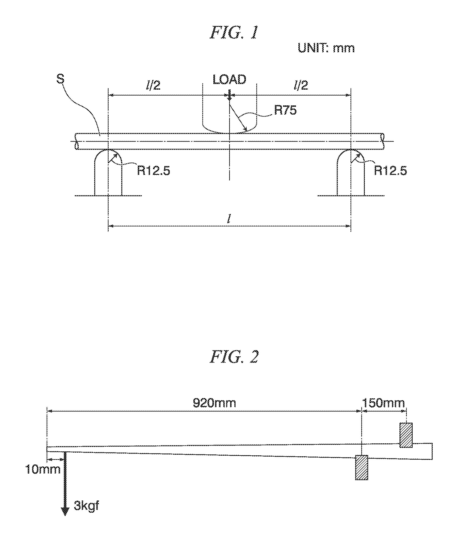
A problem in the weight lightening of the golf club shaft is a balance between light weight and strength (three-point bending strength (referred to as SG type three-point bending strength reference in Japan; SG type three-point bending strength test complies with a three-point bending test method prescribed by Consumer Product Safety Association), see FIG. 1).

Method used


Image

  • Golf club shaft for wood club
  • Golf club shaft for wood club
  • Golf club shaft for wood club

Examples


example 1

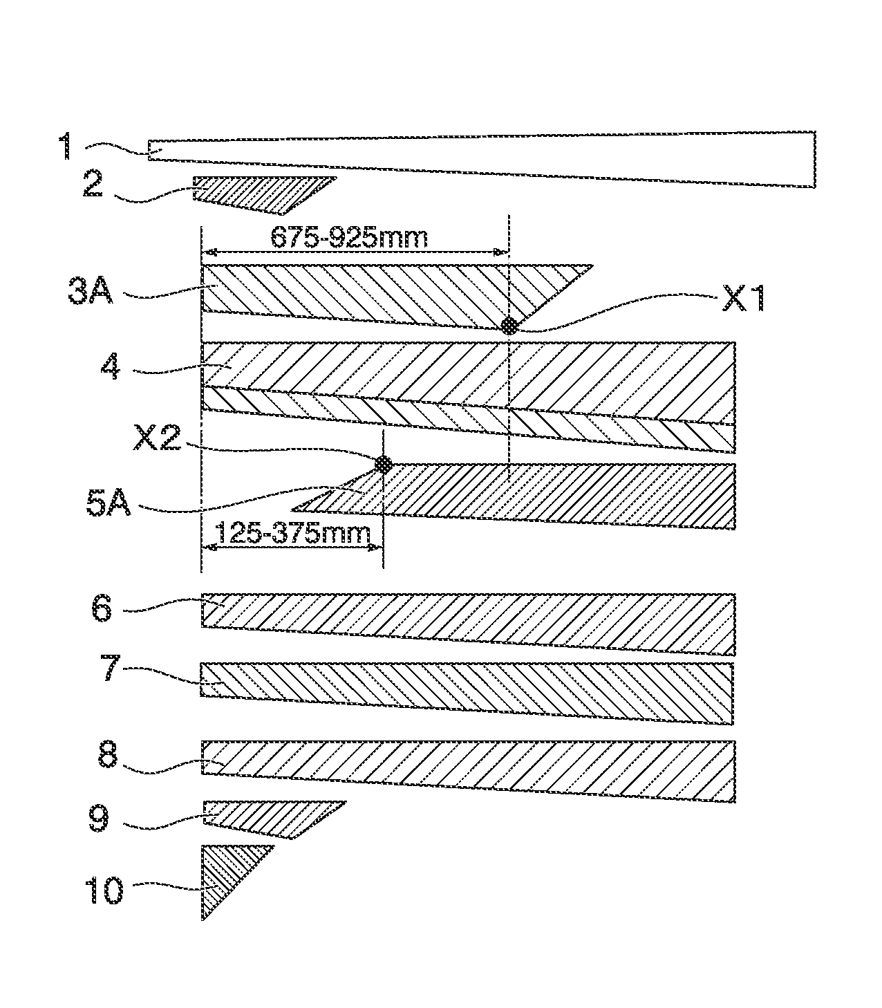
[0238]FIG. 8 is a schematic diagram illustrating a laminated structure in Example 1 of the invention. In Example 1, a shaft was prepared in the same manner as in Comparative Example 1 except that hoop layers were respectively modified as follows.[0239]In a first hoop layer 3A (prepreg O), a position 675 mm apart from an end part of a small-diameter side becomes a winding end position.[0240]In a second hoop layer 5A (prepreg P), a position 375 mm apart from the end part of the small-diameter side becomes a winding start position.

example 2

[0241]In Example 2, a shaft was prepared in the same manner as in Comparative Example 2 except that hoop layers were respectively modified as follows.[0242]In a first hoop layer 3A (prepreg P), a position 675 mm apart from an end part of a small-diameter side becomes a winding end position.[0243]In a second hoop layer 5A (prepreg P), a position 375 mm apart from the end part of the small-diameter side becomes a winding start position.

example 3

[0244]In Example 3, a shaft was prepared in the same manner as in Comparative Example 3 except that hoop layers were respectively modified as follows.[0245]In a first hoop layer 3A (prepreg P), a position 675 mm apart from an end part of a small-diameter side becomes a winding end position.[0246]In a second hoop layer 5A (prepreg P), a position 375 mm apart from the end part of the small-diameter side becomes a winding start position.

[0247]In Examples 1 to 3, a bias layer 4 was configured to have exactly two layers over a full length as in Comparative Examples 1 to 3. Since the bias layer 4 is originally configured such that two sheets are attached to each other, the bias layer is provided to have substantially four layers. By forming in this way, it is possible to stably obtain the strength even when the strength is measured at any position in a circumferential direction.


PUM


Abstract

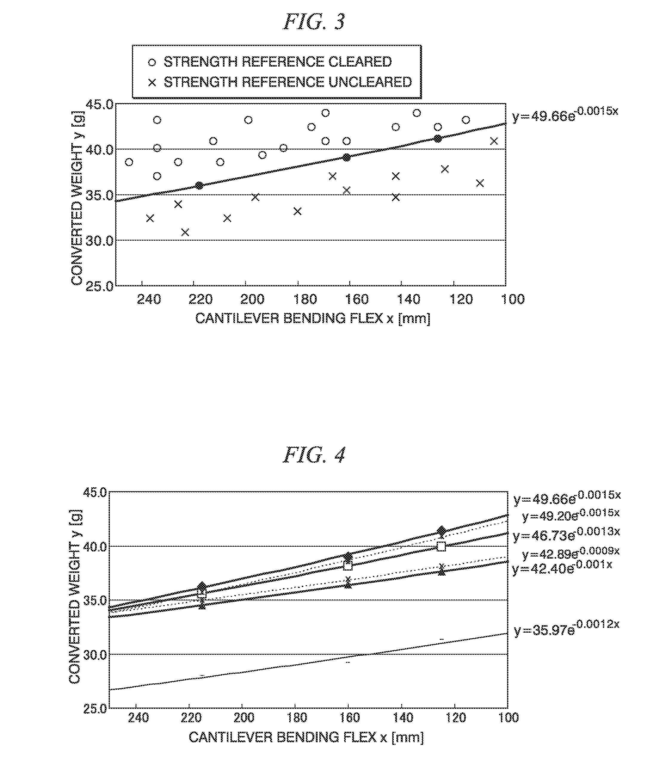
A golf club shaft which satisfies strength and is lightweight is provided by the present invention. This golf club shaft comprises one or more fiber-reinforced resin layers, and is characterized by satisfying the following relationship (1), wherein x [mm] is the displacement in a cantilever bending test, M [g] is the mass of the golf club shaft, and L [mm] is the length thereof, and by satisfying the following strength standard values [1]-[4]: M×(L / 1168)<49.66 e−0.0015x (relationship 1); [1] the three-point bending strength at T-90 (the position 90 mm apart from the smaller-diameter end) is 800 N or higher; [2] the three-point bending strength at T-175 (the position 175 mm apart from the smaller-diameter end) is 400 N or higher; [3] the three-point bending strength at T-525 (the position 525 mm apart from the smaller-diameter end) is 400 N or higher; and [4] the three-point bending strength at B-175 (the position 175 mm apart from the larger-diameter end) is 400 N or higher.

Description

TECHNICAL FIELD[0001]The present invention relates to a wood golf club shaft formed of fiber-reinforced resin layers.[0002]This application is based upon and claims the benefit of priority from the prior Japanese Patent application No. 2012-122094, filed on May 29, 2012, the entire contents of which are incorporated herein by reference.BACKGROUND ART[0003]After a rule of rebound regulations is applied to a golf club head, a method of improving a carry distance is progressing in shaft performance. Most effective means to cover repulsive force of the golf club head is to make a shaft long. A club head speed can be increased by making the shaft long. However, an inertia moment of the club is increased only by simply making the shaft long, so that players may feel the club “heavy” at the time of swing. There is a technique for lightening weight of the club head as a means to solve this problem, but when the weight of the club head is lightened, an impulse is reduced at the time of an im...

Claims


Application Information

Patent Timeline
Patent Type & Authority Patents(United States)
IPC IPC(8): A63B53/10
CPCA63B53/10A63B60/42A63B2209/023A63B60/00A63B2209/02A63B60/02Y10S273/23
Inventor SHIMONO, SATOSHIKANEKO, TAKASHIKISHI, MASAHIRO
Owner MITSUBISHI CHEM CORP
Learn More