Thrust ball bearing cage and thrust ball bearing

a thrust ball bearing and thrust ball bearing technology, applied in the direction of shafts and bearings, rotary bearings, rolling contact bearings, etc., can solve the problem of likely damage to claw-shaped protrusions, and achieve the effect of less likely damage, less likely damage, and improved lubricity of sliding portions

Active Publication Date: 2016-07-12
JTEKT CORP
View PDF12 Cites 1 Cited by
  • Summary
  • Abstract
  • Description
  • Claims
  • Application Information

AI Technical Summary

Benefits of technology

[0010]An object of the invention is to provide a thrust ball bearing cage that is less likely to be damaged when balls are inserted into pockets even if a material having high rigidity is used for the cage, and is also capable of improving lubricity of a sliding portion, and to provide a thrust ball bearing having a cage that is less likely to be damaged and is also capable of improving the lubricity of the sliding portion.

Problems solved by technology

The inventor found that the conventional cage had the following problems.
When the balls are fitted in the pockets, the balls and the claw-shaped protrusions are therefore brought into contact with each other, whereby the claw-shaped protrusions are likely to be damaged.

Method used


Image

  • Thrust ball bearing cage and thrust ball bearing
  • Thrust ball bearing cage and thrust ball bearing
  • Thrust ball bearing cage and thrust ball bearing

Examples


Embodiment Construction

[0016]Embodiments of the invention will be described in details below with reference to the drawings.

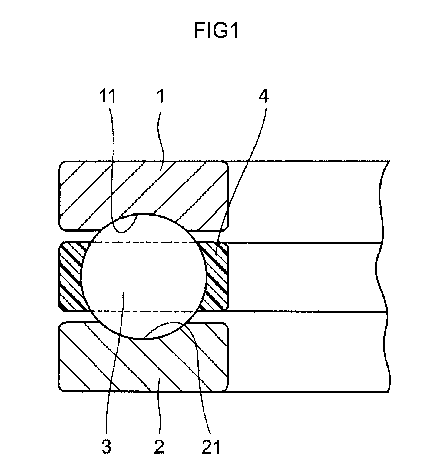
[0017]FIG. 1 is a schematic sectional view of a thrust ball bearing according to an embodiment of the invention, taken along the radial direction of the thrust ball bearing.

[0018]The thrust ball bearing (hereinafter referred to as a ball bearing) can receive an axial load from a rotary shaft of a refrigerator compressor, for example, and can be disposed in the presence of compressor oil as a refrigerant. The ball bearing includes a first bearing ring 1, a second bearing ring 2, a plurality of balls 3, and an annular thrust ball bearing cage (hereinafter referred to as a cage) 4 made of polyphenylene sulfide (PPS) resin.

[0019]The first bearing ring 1 has an annular raceway groove 11 on an end face located on one axial side, and the second bearing ring 2 has an annular raceway groove 21 on an end face located on the other axial side. The cage 4 is formed by injection molding. The balls...


PUM


Abstract

An end in an axial direction of a cage includes a first end face located so as to surround a pocket, a plurality of claw-shaped protrusions that protrude from a periphery of the pocket in a first end face outward in an axial direction and toward a center of the pocket and extend along the periphery at intervals, and a second end face that is connected to an end of the first end face, which is located on the opposite side of the first end face from the pocket side, via a step and is located further outward in the axial direction than the first end face. A recess is defined by the claw-shaped protrusions, the first end face, and the step.

Description

INCORPORATION BY REFERENCE[0001]The disclosure of Japanese Patent Application No. 2014-043059 filed on Mar. 5, 2014 including the specification, drawings and abstract, is incorporated herein by reference in its entirety.BACKGROUND OF THE INVENTION[0002]1. Field of the Invention[0003]The invention relates to a thrust ball bearing cage. The invention also relates to a thrust ball bearing.[0004]2. Description of Related Art[0005]As a conventional thrust ball bearing cage (hereinafter referred to as a cage), there is a cage described in Japanese Patent Application Publication No. 2008-223970 (FIG. 3 in JP 2008-223970 A). The cage is formed of an annular member, and the annular member has a plurality of pockets arranged at intervals and extending through the annular member in an axial direction[0006]Each pocket has a plurality of claw-shaped protrusions, and the claw-shaped protrusions protrude at a periphery of an opening of the pocket so as to be formed in a convex shape. The claw-shap...

Claims


Application Information

Patent Timeline
Patent Type & Authority Patents(United States)
IPC IPC(8): F16C19/30F16C33/38F16C19/12
CPCF16C33/3887F16C19/305F16C33/6651F16C33/6681F16C19/10F16C33/3856
Inventor SAKAMOTO, YASUHIRO
Owner JTEKT CORP
Why Eureka
Try Eureka