Wearable transdermal neurostimulator having cantilevered attachment

a transdermal neurostimulator and cantilever technology, applied in the field of non-invasive neuromodulation, can solve the problems of ineffective, uncomfortable and easy-to-use neurostimulators, lack of neurostimulators that are effective, comfortable and easy-to-use, especially in a non-clinical (e.g., home) setting,

Active Publication Date: 2016-07-19
THYNC GLOBAL INC
View PDF170 Cites 16 Cited by
  • Summary
  • Abstract
  • Description
  • Claims
  • Application Information

AI Technical Summary

Benefits of technology

[0019]In general, the apparatuses described herein may be lightweight. For example, the neurostimulator may weigh less than 7 ounces (e.g., less than 7 ounces, 6 ounces, 5 ounces, 4 ounces, 3 ounces, 2 ounces).
[0042]As mentioned, in general these devices are lightweight, and in particular, the apparatus may weigh less than 5 ounces. The weight may be non-uniformly distributed within the apparatus; in particular in neurostimulator apparatuses configured to cantilever off of an electrode apparatus, the weight (and / or thickness) of the neurostimulator apparatus may be greater at or near the end of the neurostimulator apparatus above the connectors, so that the lighter end (which may also be thinner) is opposite this end / edge region. Counter intuitively, in some variations this may be reversed, so that the thicker and / or heavier end / edge region of the neurostimulator apparatus is positioned opposite from the region of electrical and mechanical attachment by the connectors; this configuration may be unexpectedly advantageous in allowing the device to conform to the subject's head while remaining securely attached to the electrode apparatus. This configuration may also allow separation between the connectors (e.g., snap receivers) and internal electrical circuitry and / or power storage (e.g., battery) components.
[0071]The first and second connectors may secure a first edge region of the user-facing surface to the electrode apparatus while permitting a second edge region of the user-facing surface that is opposite from the first edge region to float relative to the electrode apparatus. As discussed above, the first and second connectors may comprise snap receivers. The first and second connectors may be separated by any appropriate length, typically between 0.5 and 1 inch, but particularly 0.6 and 0.9 inches and more particularly 0.7 and 0.8 inches (e.g., between about 0.7 and 0.75 inches). As described above, such cantilevered apparatuses may be lightweight (e.g., may weigh less than 5 ounces), and may be relatively thin (e.g., the housing may be less than 30 mm thick, less than 20 mm thick, less than 15 mm thick, less than 11 mm thick, etc.).

Problems solved by technology

Noninvasive neuromodulation technologies that affect neuronal activity can modulate neural activity and potentially alter behavior, cognitive states, perception, and motor output without requiring an invasive procedure.
To date, the majority of transdermal non-invasive neuromodulatory devices apply electrical energy to a subject's skin using one or more electrodes that typically attach to the neurostimulator via a cord or cable, which can be long and awkward to wear, particularly in a non-clinical or non-research setting.
Despite the research to date on TES neuromodulation, existing systems and methods for delivering TES are lacking.
In particular, neurostimulators that are effective, comfortable and easy-to-use, e.g., easy to apply and remove, particularly in a non-clinical (e.g., home) setting, have been lacking.
Although a handful of small, lightweight and presumably wearable neuromodulation devices have been described, none of these systems are adapted for use with electrodes (e.g., disposable electrode assemblies) for applying energy to a user's head.
In particular, none of these systems may be secured to a separate electrode assembly so that the neurostimulator may be well-secured to the user's head (or other body region) for a variety of sizes of users.

Method used


Image

  • Wearable transdermal neurostimulator having cantilevered attachment
  • Wearable transdermal neurostimulator having cantilevered attachment
  • Wearable transdermal neurostimulator having cantilevered attachment

Examples


Embodiment Construction

[0150]The following description of the various embodiments of the invention is not intended to limit the invention to these embodiments, but rather to enable any person skilled in the art to make and use this invention. Disclosed herein are methods and apparatuses, and systems for user control of neurostimulation waveforms.

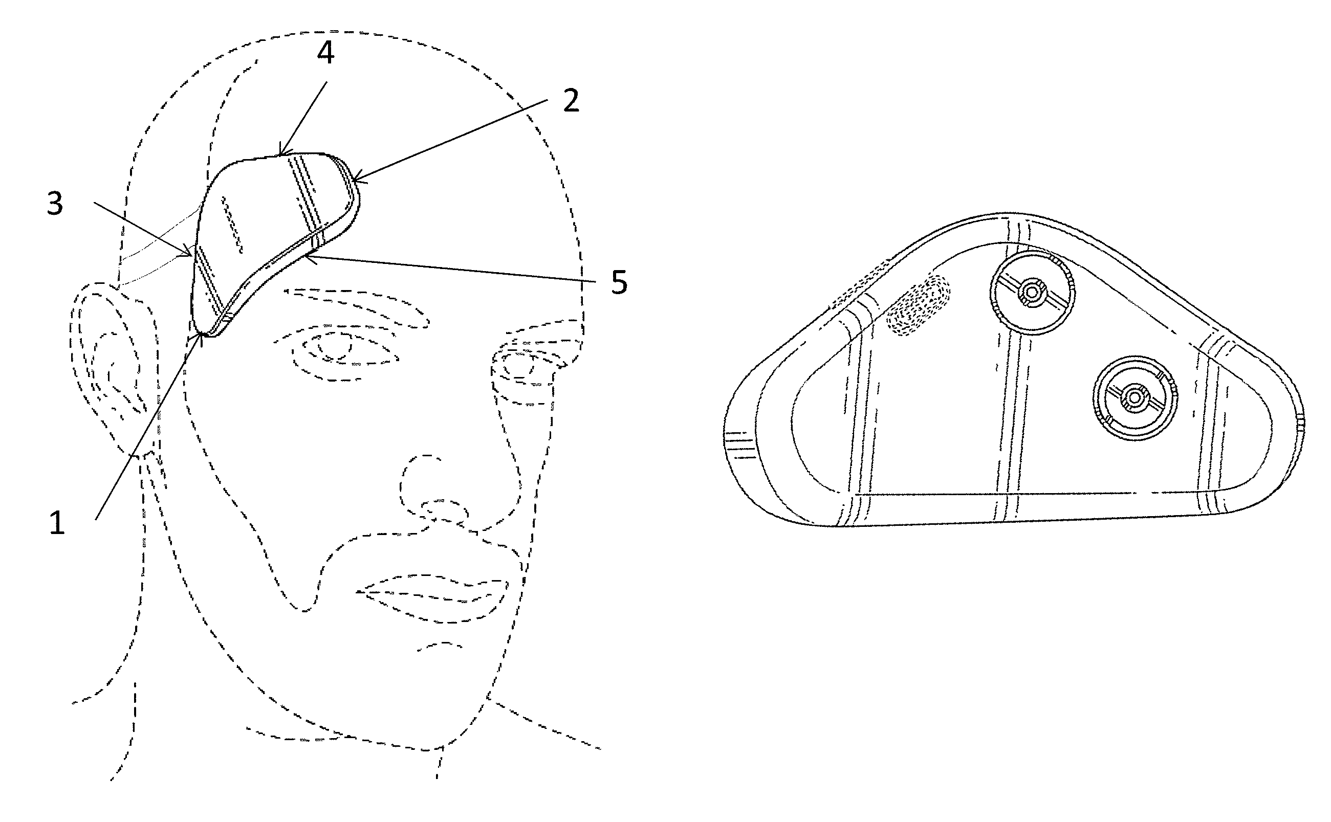
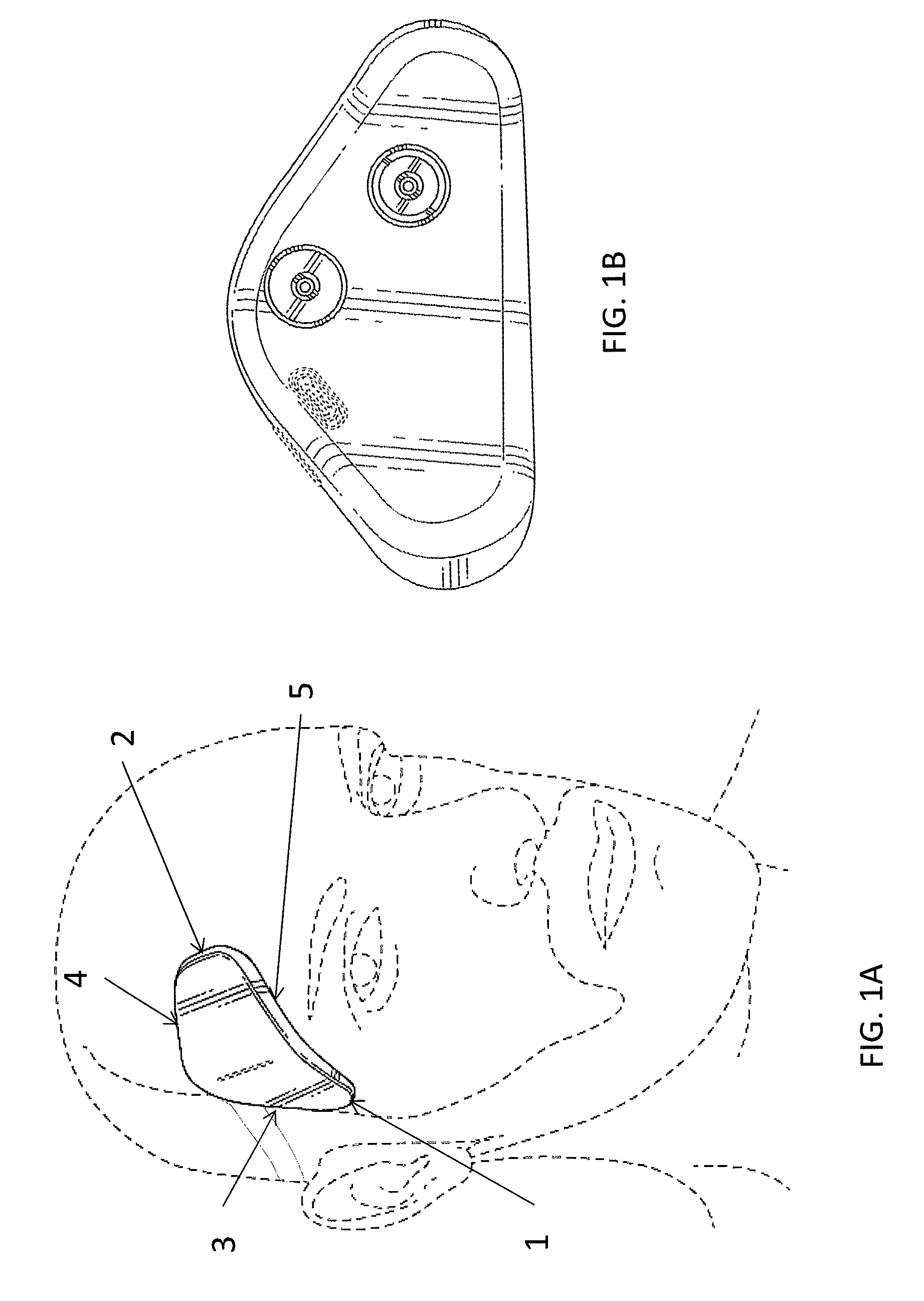
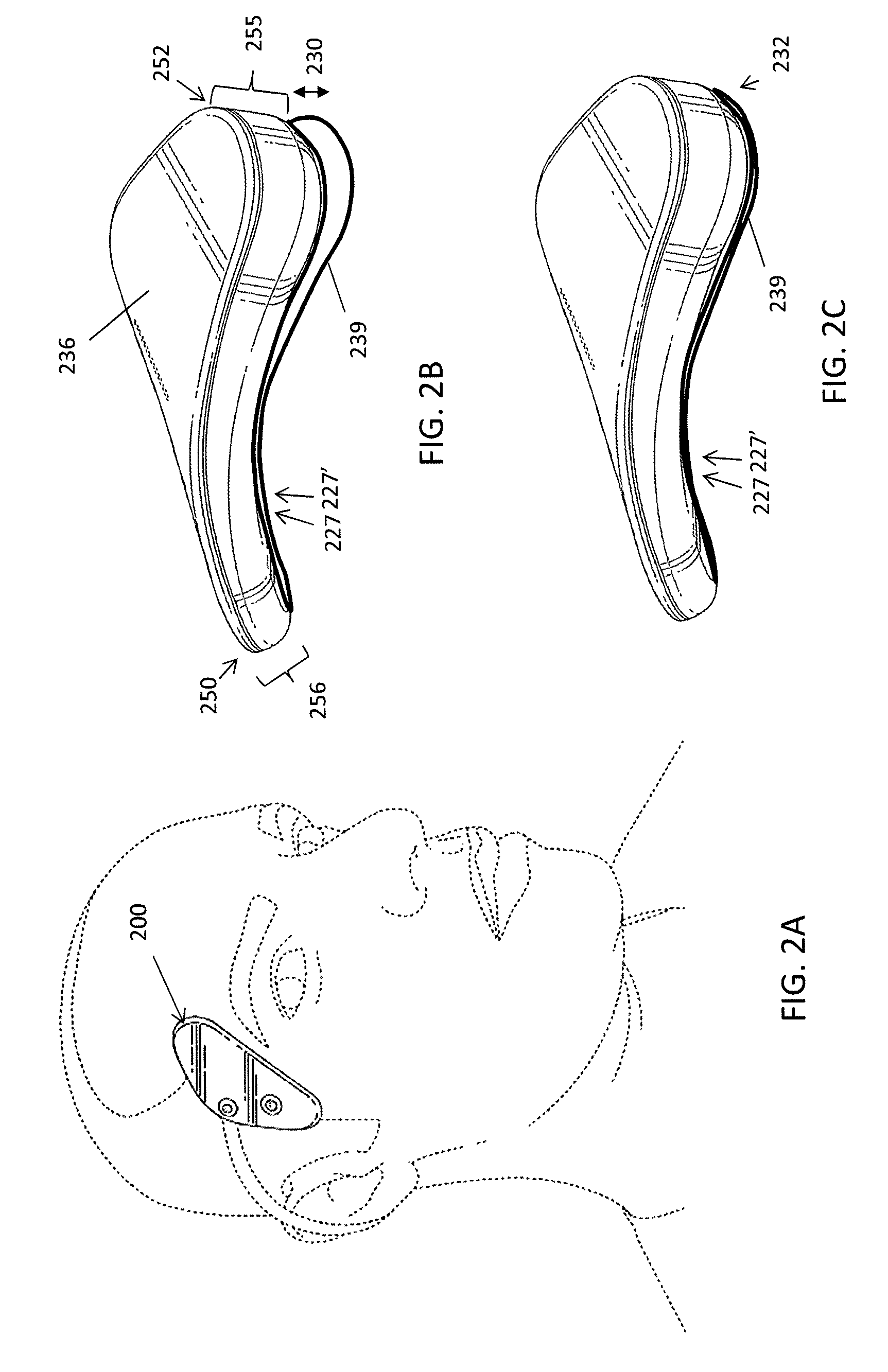
[0151]Lightweight and wearable apparatuses for applying transdermal electrical stimulation and methods of using them for inducing a cognitive effect are described. These apparatuses are typically self-contained, lightweight, and wearable devices and / or systems. The lightweight and wearable transdermal electrical stimulation apparatus for inducing a cognitive effect in a subject may generally include hardware, software and / or firmware components that are configured to generate appropriate control sequences for the device, transmit signals to a current or voltage source and / or conditioner, and connect to electrodes that are configured to be placed on a user for gene...


PUM


Abstract

Neurostimulator apparatuses for applying transdermal electrical stimulation that may be comfortably and securely worn on a variety of head shapes and sizes. The apparatuses and methods of using them described herein may be lightweight and wearable and configured to be attached at one end of a patient-facing surface of the apparatus by a cantilevered attachment so that an opposite end of the surface is free to float relative to the user's head. The cantilevered attachment may include two or more connectors spaced apart along an edge region of the patient-facing surface in an optimal arrangement to secure the neurostimulator in place. The neurostimulator apparatuses described herein may be secured to a separate or integral electrode assembly that may adhesively secure to the subject's head. The patient-facing surface of the neurostimulator may also be curved and twisted specifically for use at the temple / forehead region of a diverse population of potential users.

Description

CROSS REFERENCE TO RELATED APPLICATIONS[0001]This patent application claims priority to U.S. Provisional Patent Application No. 62 / 002,910, titled “TRANSDERMAL ELECTRICAL STIMULATION ELECTRODE DEGRADATION DETECTION SYSTEMS AND METHODS OF USING THEM,” and filed May 25, 2014; U.S. Provisional Patent Application No. 62 / 076,459, titled “CANTILEVER ELECTRODES FOR TRANSDERMAL AND TRANSCRANIAL STIMULATION,” and filed Nov. 6, 2014; U.S. Provisional Patent Application No. 62 / 099,950, titled “CANTILEVER ELECTRODES FOR TRANSDERMAL AND TRANSCRANIAL STIMULATION,” and filed Jan. 5, 2015; U.S. Provisional Patent Application No. 62 / 075,896, titled “SYSTEMS AND METHODS FOR NEUROMODULATION,” and filed Nov. 6, 2014; U.S. Provisional Patent Application No. 62 / 099,960, titled “METHODS AND APPARATUSES FOR USER CONTROL OF NEUROSTIMULATION,” and filed Jan. 5, 2015; U.S. Provisional Patent Application No. 62 / 100,022, titled “WEARABLE TRANSDERMAL NEUROSTIMULATOR,” and filed Jan. 5, 2015. Each of these applic...

Claims


Application Information

Patent Timeline
Patent Type & Authority Patents(United States)
IPC IPC(8): A61N1/04A61N1/36
CPCA61N1/0456A61N1/0492A61N1/36025A61N1/025A61N1/3603
Inventor GOLDWASSER, ISYPAL, SUMON K.CHARLESWORTH, JONATHANLAW, WINGHAMLIN, JAY FREDERICKWETMORE, DANIEL Z.TYLER, WILLIAM J.JEFFERY, DOUGLAS
Owner THYNC GLOBAL INC
Why Eureka
Try Eureka