Damping valve

a technology of damping valve and damping force, which is applied in the direction of shock absorbers, liquid based dampers, vibration dampers, etc., can solve the problems of insufficient ease of thrust vibration, insufficient damping force decrease effect, and insufficient improvement of ride quality in vehicles, so as to reduce damping force and damping force

Active Publication Date: 2016-07-19
KYB CORP
View PDF17 Cites 1 Cited by
  • Summary
  • Abstract
  • Description
  • Claims
  • Application Information

AI Technical Summary

Benefits of technology

[0009]An object of this invention is to provide a damping valve capable of exerting a damping force decrease effect at the time of a contraction operation of a damper and improving the ride quality of a vehicle.

Problems solved by technology

In particular, upon an input of a shocking vibration of thrusting a wheel up for example when the vehicle goes over an uneven part on a road surface at the time of traveling, a damping force decrease effect cannot be sufficiently exerted.
When such vibration is inputted to the wheel, thrust vibration cannot be sufficiently eased but the thrust vibration is transmitted to a vehicle body.
Therefore, the ride quality in the vehicle cannot be sufficiently improved.

Method used


Image

  • Damping valve
  • Damping valve
  • Damping valve

Examples


first embodiment

[0020]A first embodiment will be described.

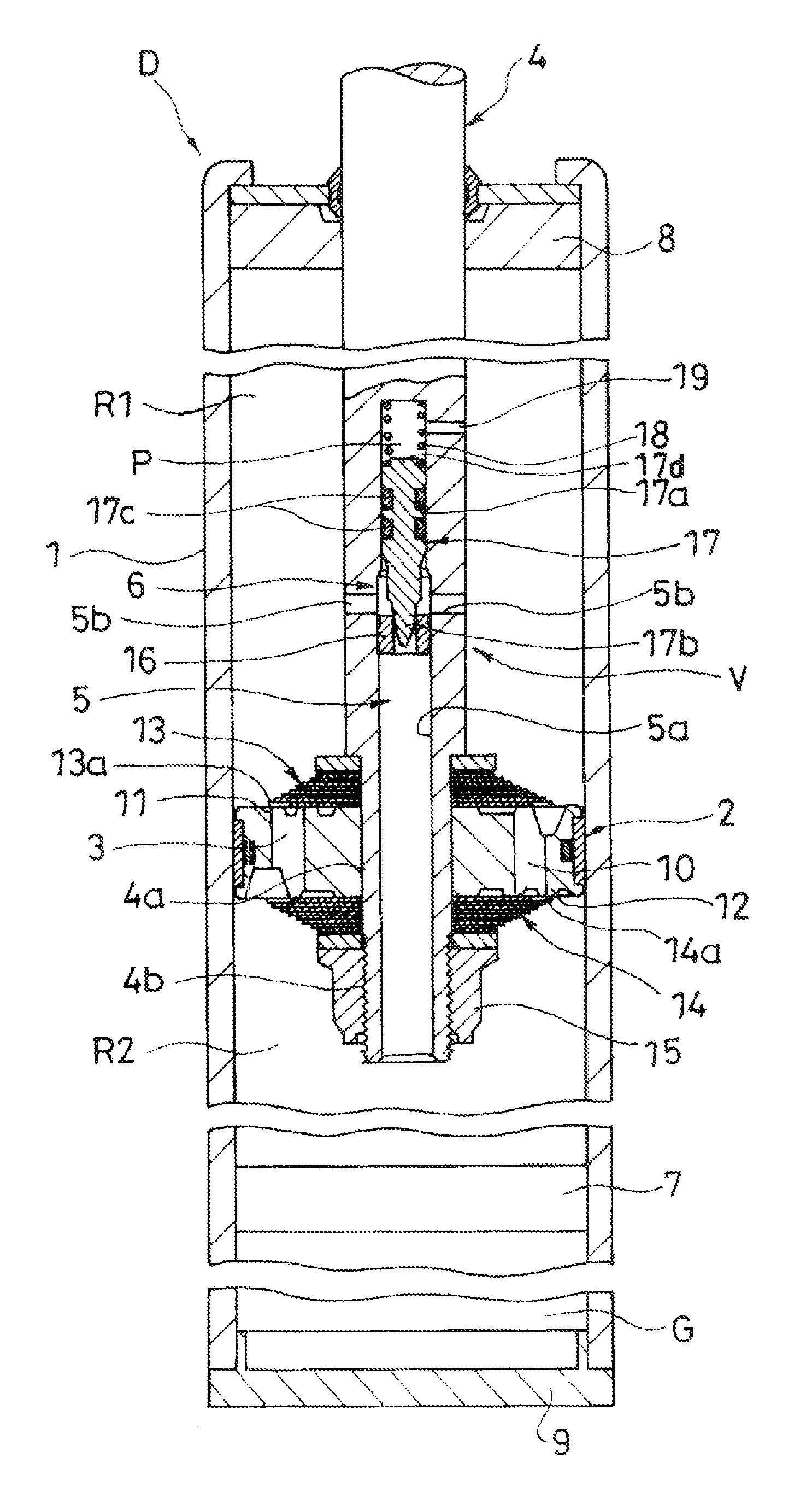
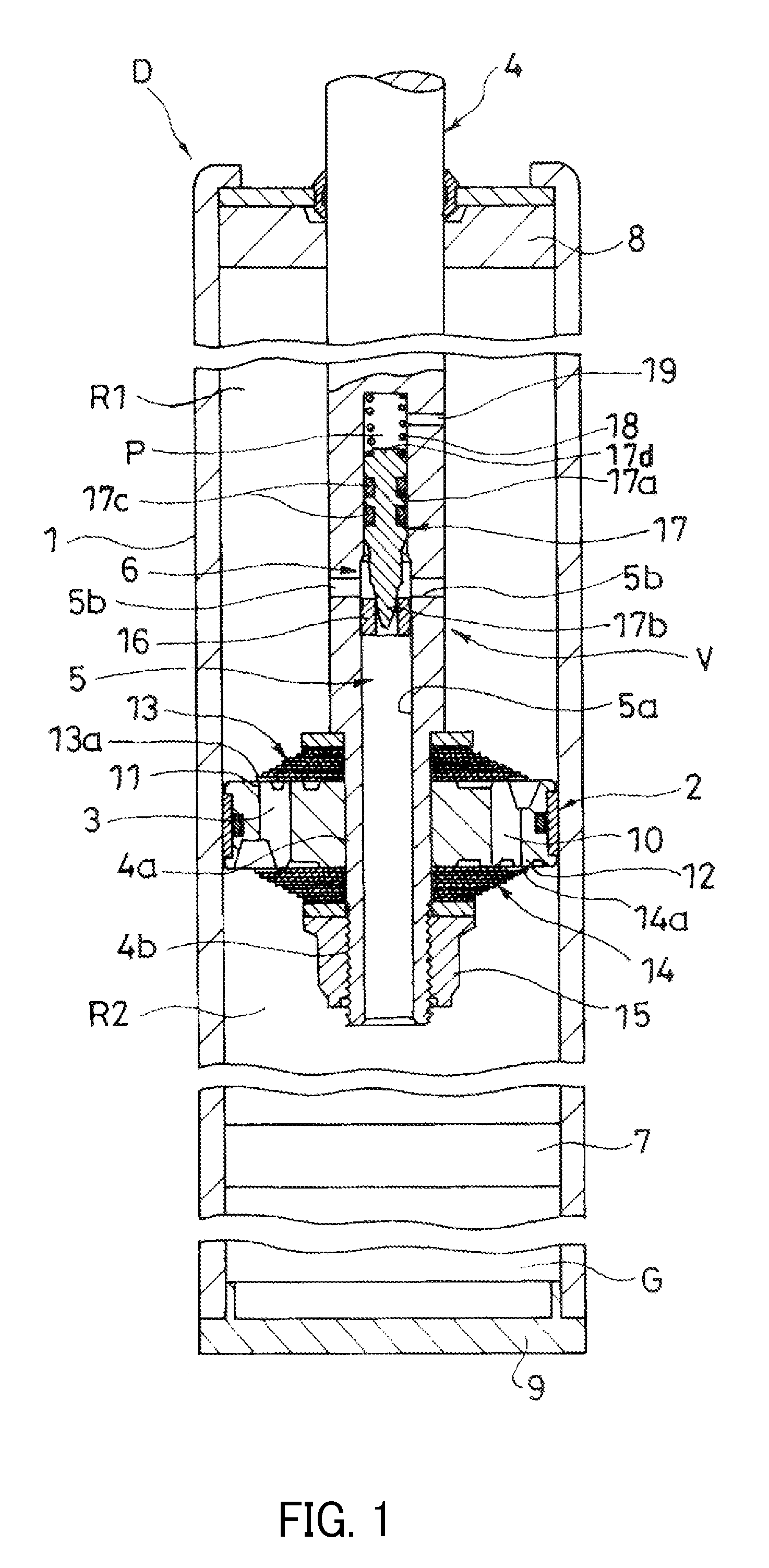
[0021]As shown in FIG. 1, a damping valve V in the present embodiment is applied to a damper D. The damping valve V includes a piston 2 movably inserted into a cylinder 1 and partitioning an interior of the cylinder 1 into an extension side chamber R1 and a pressure side chamber R2, a damping passage 3 provided in the piston 2 and communicating between the extension side chamber R1 and the pressure side chamber R2, a piston rod 4 movably inserted into the cylinder 1 and of which one end (lower end in the FIG. 1) is coupled to the piston 2, a bypass 5 provided in the piston rod 4 and communicating the pressure side chamber R2 with the extension side chamber R1 by bypassing the damping passage 3, and a relief valve 6 releasing the bypass 5 upon an action of a pressure of the pressure side chamber R2.

[0022]The damper D includes the cylinder 1, the piston 2, the piston rod 4, and a free piston 7 slidably inserted into the cylinder 1 and partiti...

second embodiment

[0054]A second embodiment will be described.

[0055]In the damper D to which the damping valve V of the first embodiment is applied, in a case where the damping characteristic at the time of the contraction operation of the damper D is tuned to match with preference of a user, there is a need for taking the damping valve V out from the damper and replacing the bias spring 18.

[0056]Thus, in the present embodiment, a damping valve V capable of easily tuning the damping characteristic at the time of the contraction operation of the damper D will be described.

[0057]As shown in FIG. 3, the damping valve V in the present embodiment is applied to the damper D. Since configurations of part of the damper D and the damping valve V are the same as the first embodiment, the description thereof will be omitted, and only different parts will be described.

[0058]In the present embodiment, the relief valve 6 further includes an adjustment mechanism 20 adjusting the bias force of the bias spring 18, an...

third embodiment

[0071]A third embodiment will be described.

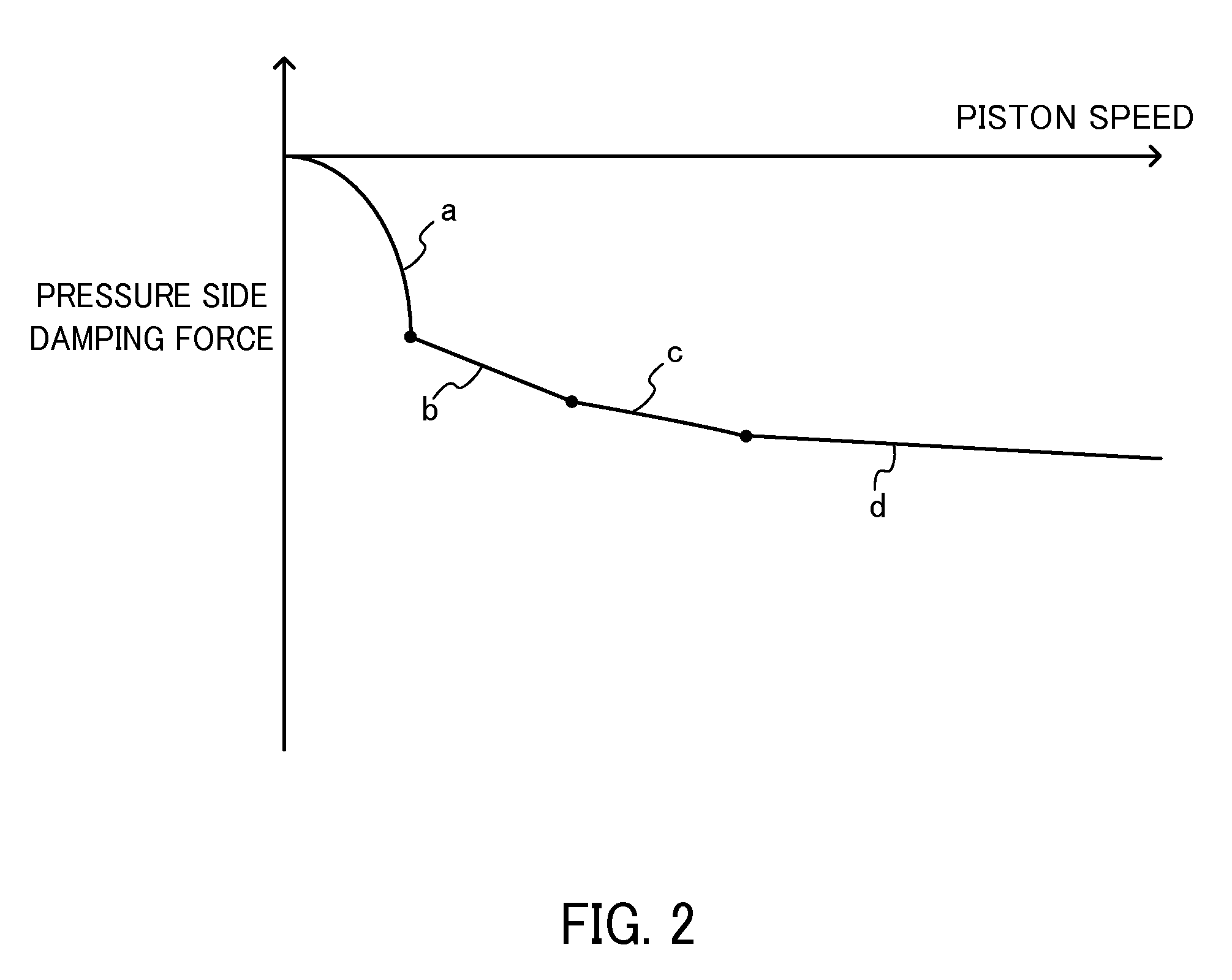
[0072]In the first embodiment, among the damping characteristic of the damper D after opening the relief valve 6, a retreat displacement amount of the valve body 17 from the annular valve seat 16 after opening the relief valve 6 is considered to be managed by controlling the pressure in the back pressure chamber P in addition to changing a spring constant of the bias spring 18. The pressure in the back pressure chamber P is controlled by a magnitude of resistance applied to the passing fluid by the throttle 19, specifically by the flow passage area of the throttle 19.

[0073]Therefore, in the damping valve V of the first embodiment, by setting the flow passage area of the throttle 19 to an area to realize a target damping characteristic in advance, the damping characteristic can be tuned.

[0074]It should be noted that when the damping characteristic is tuned only by the spring constant of the bias spring 18, not only the gradient of the dampin...


PUM


Abstract

A damping valve includes a piston, a damping passage, a piston rod, a bypass, and a relief valve, and the bypass includes a valve hole extending in the axial direction of the piston rod and a horizontal hole opening from a side part of the piston rod and leading to the valve hole, and the relief valve includes an annular valve seat provided on the side of a pressure side chamber with respect to an opening of the horizontal hole, a valve body slidably inserted on the side of an extension side chamber with respect to the annular valve seat and partitioning a back pressure chamber in the valve hole, a bias spring biasing the valve body toward the annular valve seat, and a throttle communicating the back pressure chamber with the extension side chamber.

Description

TECHNICAL FIELD[0001]The present invention relates to a damping valve.BACKGROUND ART[0002]As a conventional damping valve, for example, there is a known piston valve provided in a piston portion of a damper for a vehicle. The piston valve has an annular leaf valve laminated on an outlet end of a port which is provided in the piston portion, and the port is opened and closed by this leaf valve.[0003]In the above piston valve, by fixing and supporting the inner circumferential side of the leaf valve and warping the outer circumferential side, the port is opened and closed by the leaf valve. When warping rigidity of the leaf valve is reduced, a damping force in a low speed region of piston speed is excessively decreased, and when the warping rigidity is increased, a damping force in a mid-high speed region of the piston speed is excessively increased. Thus, ride quality in the vehicle is not easily satisfied in all the speed regions.[0004]Therefore, JP9-291961A discloses a valve struct...

Claims


Application Information

Patent Timeline
Patent Type & Authority Patents(United States)
IPC IPC(8): F16F9/34F16F9/18F16F9/46F16F9/512
CPCF16F9/464F16F9/5126F16F9/182F16F9/34F16F9/3405
Inventor TANAKA, KAZUHIRO
Owner KYB CORP
Why Eureka
Try Eureka