Hydraulic shock absorber

a hydraulic shock absorber and double-rod technology, applied in the direction of shock absorbers, mechanical equipment, transportation and packaging, etc., can solve the problems of high sealing ability of materials, disadvantages of hydraulic shock absorbers in improving so as to improve the ride quality of vehicles, prevent cavitation, and increase the operability of piston rods

Active Publication Date: 2016-08-25
YAMAHA MOTOR CO LTD
View PDF5 Cites 1 Cited by
  • Summary
  • Abstract
  • Description
  • Claims
  • Application Information

AI Technical Summary

Benefits of technology

[0028]When the piston moves with respect to the cylinder in the hydraulic shock absorber according to preferred embodiments of the present invention, hydraulic oil flows through the second hydraulic oil passage at a flow rate equivalent to the difference between the cross-sectional areas of the sliding portions of the main and sub piston rods. The total cross-sectional area of this second hydraulic oil passage is equal to or larger than the difference between the cross-sectional areas of the sliding portions of the main and sub piston rods. Accordingly, a large amount of hydraulic oil smoothly flows through the second hydraulic oil passage as the piston moves, so no cavitation occurs in the oil chamber even when the moving velocity of the piston is high.
[0029]Accordingly, hydraulic shock absorbers according to preferred embodiments of the present invention increase the operability of the piston rod, and are able to provide an initial set load to the shock-absorbing rubber of a vehicle while preventing cavitation in the oil chamber. Consequently, preferred embodiments of the present invention provide hydraulic shock absorbers that are able to improve the ride quality of a vehicle because a damping force is generated with high responsiveness to the behavior of the vehicle.

Problems solved by technology

The hydraulic shock absorber disclosed in Japanese Patent No. 4996957 has the following difficulty in improving the ride quality of a vehicle when used in the vehicle.
The first problem is that a material having a high sealing ability must be used as the sealing member to seal the portion between the pipe and sub piston rod.
That is, the hydraulic shock absorber is disadvantageous in improving the ride quality of a vehicle because a sliding resistance generated when the sealing member comes into contact with the piston rod is high.
However, even the hydraulic shock absorber disclosed in Japanese Patent Publication No. 48-21039 cannot eliminate the following second problem.
The second problem is that the responsiveness decreases because the hydraulic shock absorber expands or contracts after the shock-absorbing rubber deforms due to the displacement of the body of the vehicle.
That is, since the hydraulic shock absorber operates later than the displacement of the body of the vehicle, the ride quality of the vehicle cannot be improved.
Unfortunately, this configuration cannot be applied to each of the hydraulic shock absorbers described in Japanese Patent No. 4996957 and Japanese Patent Publication No. 48-21039 for a structural reason.
However, no sufficient passage area is able to be provided in each of the hydraulic shock absorbers described in Japanese Patent No. 4996957 and Japanese Patent Publication No. 48-21039.
It is difficult to provide a communication path having a sufficient passage area in this pipe.
Since a large amount of hydraulic oil cannot flow through this communication path when the piston moves, cavitation may occur in the oil chamber.
The communication path cannot have a large cross-sectional area by which no cavitation occurs, because the cross-sectional area is restricted by the thickness of the pipe.
Accordingly, a large amount of hydraulic oil cannot freely flow between the second and third oil chambers of this hydraulic shock absorber.

Method used


Image

  • Hydraulic shock absorber
  • Hydraulic shock absorber
  • Hydraulic shock absorber

Examples


first preferred embodiment

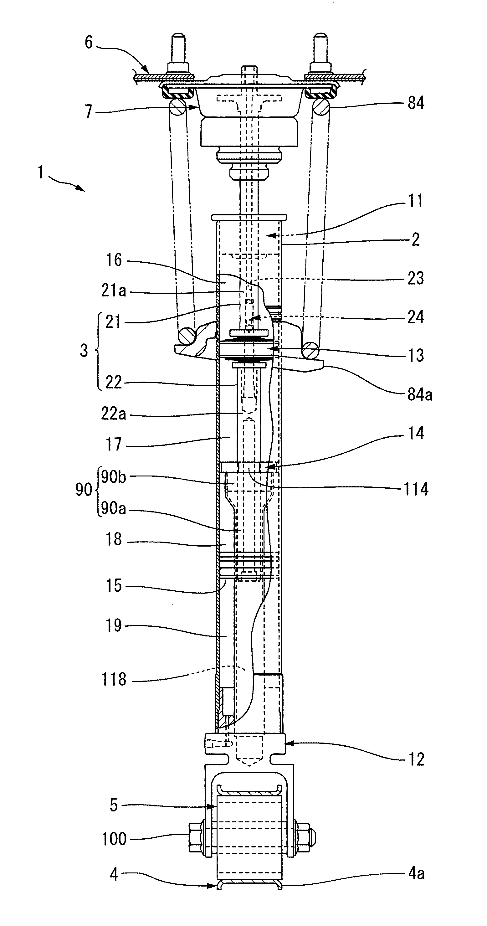
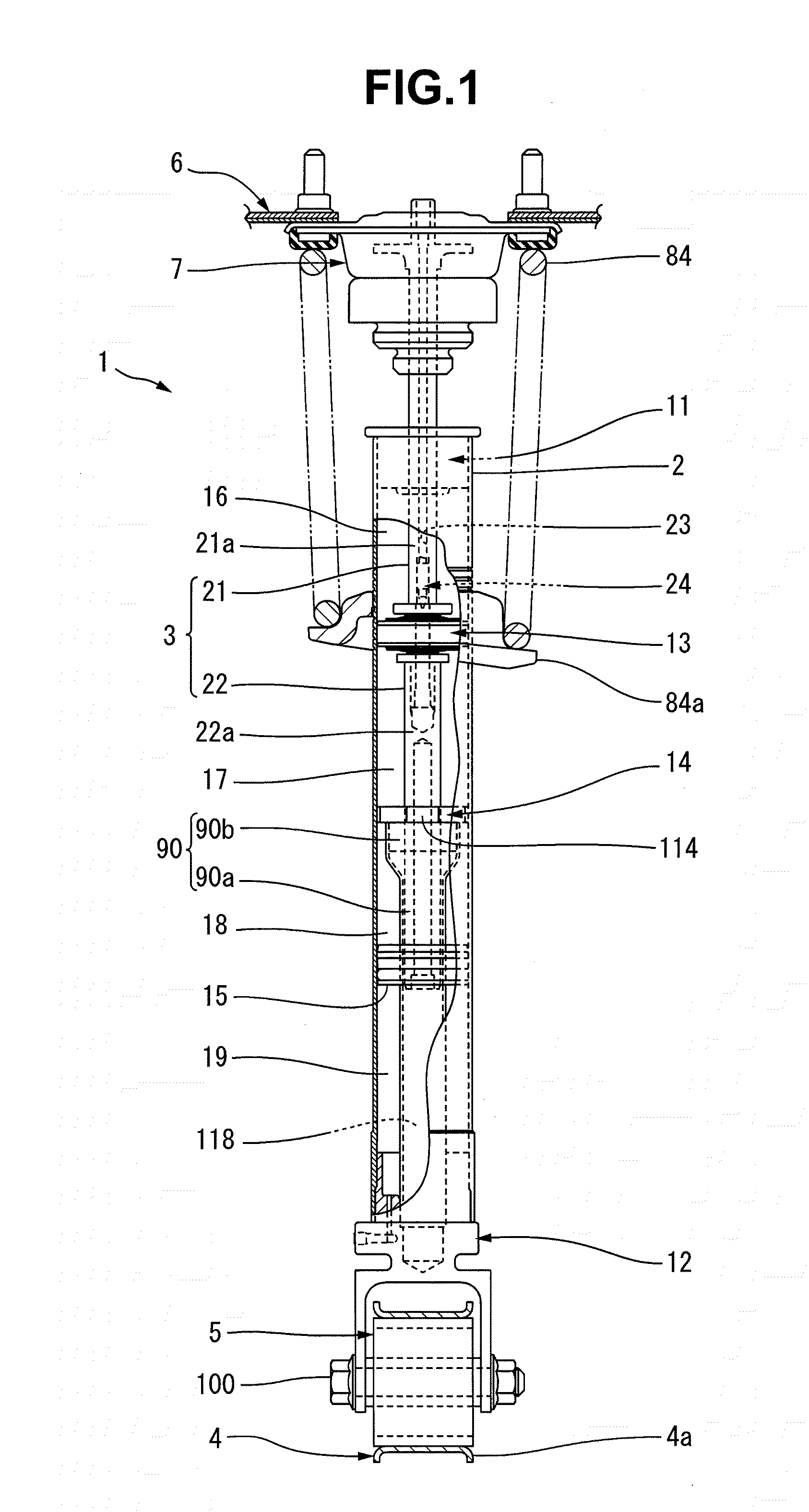
[0045]A first preferred embodiment of a hydraulic shock absorber according to the present invention will be explained in detail below with reference to FIGS. 1 to 9C.

[0046]A hydraulic shock absorber 1 shown in FIG. 1 includes a cylinder 2, and a piston rod 3 projecting from one end portion (the upper end portion in FIG. 1) of the cylinder 2. The hydraulic shock absorber 1 according to the present preferred embodiment is preferably used in a vehicle such as an automobile (not shown), for example. The cylinder 2 shown in FIG. 1 is connected to a member (e.g., a lower arm 4) of a suspension of the vehicle, which moves together with a wheel with respect to the body of the vehicle, via a wheel-side connecting member 5 (to be described below).

[0047]The piston rod 3 is connected to a body 6 of the vehicle via a body-side connecting member 7. Note that when installing the hydraulic shock absorber 1 in the vehicle, it is also possible to use a piston rod 3 that is connected to a member (e.g....

second preferred embodiment

[0134]The pipe and second support member may be provided as shown in FIGS. 10 and 11. The same or almost the same members as explained in FIGS. 1 to 9C are denoted by the same reference numerals in FIGS. 10 and 11, and a detailed explanation thereof will appropriately be omitted.

[0135]A pipe 90 shown in FIGS. 10 and 11 preferably has a shape having a constant outer diameter from one end to the other. A small-diameter portion 111 of a second support member 14 is elongated in the axial direction compared to that of the first preferred embodiment. The second support member 14 according to the present preferred embodiment is fixed to the pipe 90 such that the pipe 90 is fitted in the small-diameter portion 111. The pipe 90 is press-fitted, for example, in the small-diameter portion 111. An O-ring 123 that seals a portion between the small-diameter portion 111 and the outer circumferential surface of the pipe 90 is attached to the small-diameter portion 111.

[0136]The pipe 90 having a con...

third preferred embodiment

[0137]The cover member may also be provided as shown in FIG. 12.

[0138]The same or almost the same members as explained in FIGS. 1 to 11 are denoted by the same reference numerals in FIG. 12, and a detailed explanation thereof will appropriately be omitted.

[0139]A gas supply passage 131 that defines a circular recess 91 and the outside of a cover member 12 shown in FIG. 12 communicate with each other is provided in the cover member 12. One end of the gas supply passage 131 according to the present preferred embodiment opens to the inner circumferential surface of the circular recess 91. The gas supply passage 131 extends from the one end in the radial direction of the cover member 12. The other end of the gas supply passage 131 opens to the outer circumferential surface of the cover member 12. That is, the gas supply passage 131 is connected to a closed space 118 in a pipe 90 via the circular recess 91.

[0140]A rubber plug member 132 is held in the middle portion of the gas supply pas...


PUM


Abstract

A hydraulic shock absorber improves operability of a piston rod by providing an initial set load to the shock-absorbing rubber of a vehicle, and improves ride quality of the vehicle. The hydraulic shock absorber includes a cylinder, a first support member, a cover member, a main piston rod extending through the first support member, a sub piston rod, and a piston between the two piston rods. The hydraulic shock absorber further includes a free piston slidably fitted in the cylinder so that a pipe extends through the free piston. A first oil chamber and a second oil chamber on the two sides of the piston communicate with each other via a valve. A second support member partitions a second oil chamber and a third oil chamber, and the free piston partitions the third oil chamber and a gas chamber.

Description

BACKGROUND OF THE INVENTION[0001]1. Field of the Invention[0002]The present invention relates to a so-called, double-rod hydraulic shock absorber.[0003]2. Description of the Related Art[0004]Conventional hydraulic shock absorbers include a double-rod hydraulic shock absorber in which piston rods are installed on two sides of a piston. The piston rods of this double-rod hydraulic shock absorber are a main piston rod extending from the piston to one side, and a sub piston rod extending from the piston to the other side. The main piston rod extends through one of two oil chambers partitioned by the piston.[0005]The sub piston rod extends through the other one of the two oil chambers. The main piston rod projects outside a cylinder from a first support member provided in one end portion of the cylinder. The sub piston rod extends through a partition in the cylinder, and is slidably supported by this partition. Therefore, the cylinder includes a first oil chamber positioned between the p...

Claims


Application Information

Patent Timeline
Patent Type & Authority Applications(United States)
IPC IPC(8): B60G13/06F16F9/06B60G17/08
CPCB60G17/08F16F9/54F16F9/20F16F9/32B60G15/067F16F9/061B60G13/06B60G15/062B60G2500/10B60G2800/162B60G2204/128F16F9/063
Inventor YAMAZAKI, YUTAKA
Owner YAMAHA MOTOR CO LTD
Why Eureka
Try Eureka