Friction lining arrangement for a disk brake

a friction lining and disk brake technology, applied in the direction of brake types, noise/vibration control, braking elements, etc., can solve the problems of weight disadvantage and particularly unpleasant acoustic effects, and achieve the effect of efficient noise reduction and low cos

Active Publication Date: 2018-02-13
CONTINENTAL TEVES AG & CO OHG
View PDF41 Cites 1 Cited by
  • Summary
  • Abstract
  • Description
  • Claims
  • Application Information

AI Technical Summary

Benefits of technology

[0004]An aspect of the invention is to enable a lower cost and more efficient reduction in noise which does not unnecessarily increase the vehicle mass and also opens up advantageous manufacturing methods without impairing the performance characteristics and installation space requirements of a vehicle disk brake.
[0005]According to DE 39 18 369 A1, which is incorporated by reference a disc brake with at least one vibration-changing element is proposed in order to prevent braking noises. In particular, a measure is proposed which relates to a brake shoe with hammer head-shaped extensions. Accordingly, at least one additional mass is positioned rigidly on the hammer head-shaped extension of the back plate. A round steel which is fastened in a bore by a center of the hammer head serves this purpose so that resonant frequencies can be mistuned and displaced with respect to one another and ideally adjusted so that they do not amplify one another. The fastening of the round steel is carried out, for example, by gluing, riveting, pressing in, welding or screwing in into the bore of the back plate. Although the stated feature combination can in principle be realized at low cost, a further improved solution for the novel disk brakes is in demand, the vibration stimulation of which is based on changed framework conditions.

Problems solved by technology

As a function of the prevailing conditions in the individual case, noises resulting from this can arise which are undesirable as a comfort-reducing phenomenon.
In addition to the mechanical effects such as steering instability or vibrations on body components, the acoustic effects are felt to be particularly unpleasant.
One disadvantage lies in the fact that the additional mass must have comparatively large dimensions, i.e. results in weight disadvantages.

Method used


Image

  • Friction lining arrangement for a disk brake
  • Friction lining arrangement for a disk brake
  • Friction lining arrangement for a disk brake

Examples


Embodiment Construction

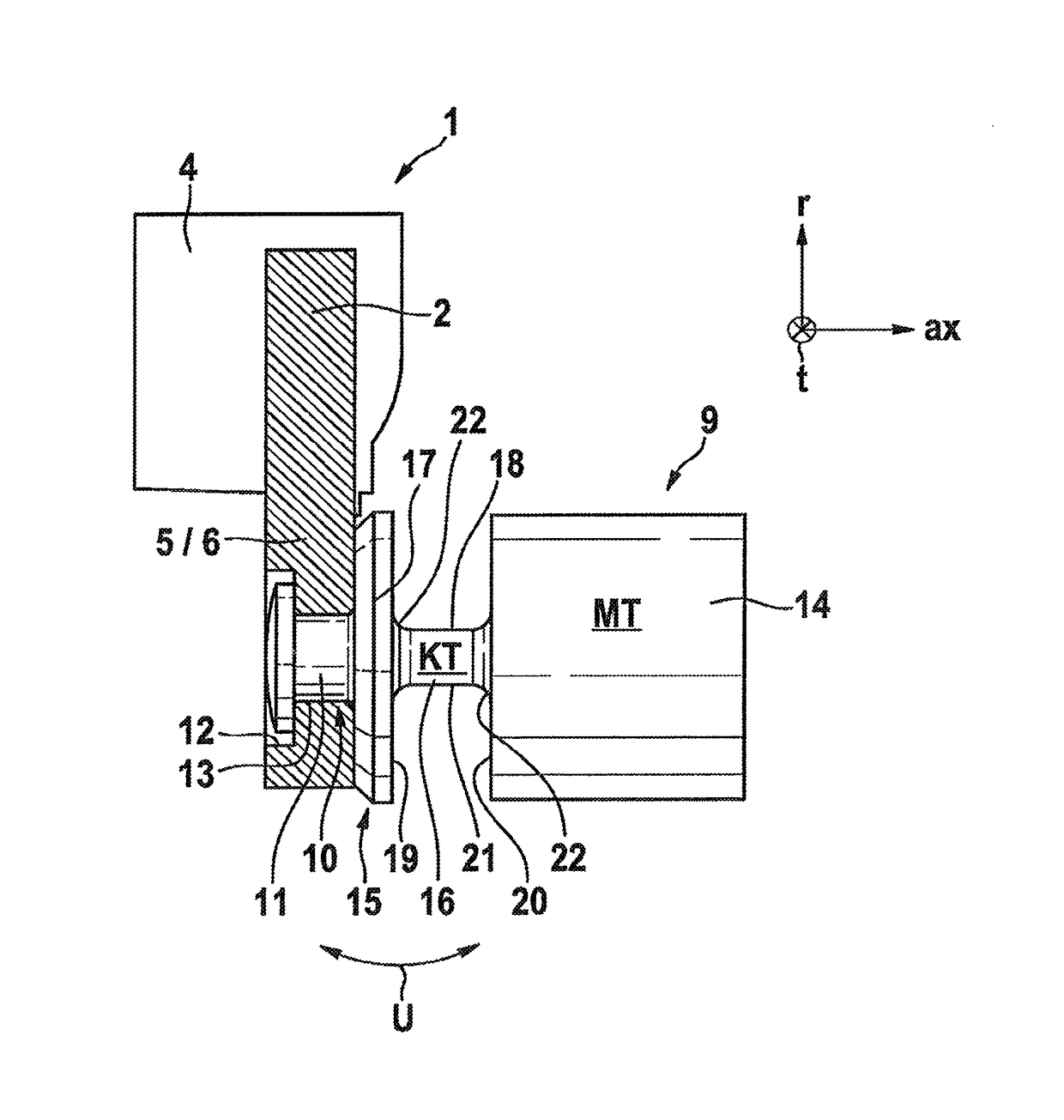
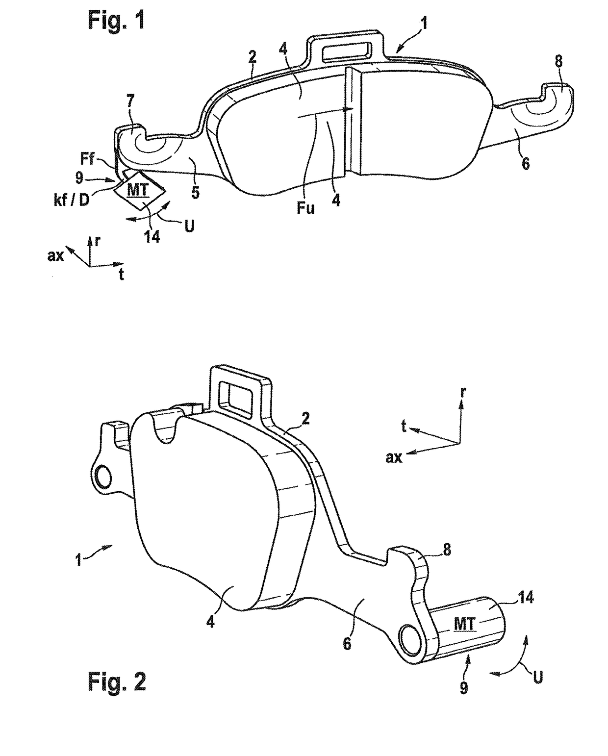
[0014]FIG. 1 shows a symmetrical friction lining 1 comprising a back plate 2. Back plate 2 is largely flat and has a central portion 3 (see FIG. 5) with a friction material 4 glued largely centrally thereon. Slim limbs (connecting portions) 5,6 which bear thickened, hammer head-shaped projections 7,8 extend in a plane with central portion 3 and projecting tangentially laterally therefrom. In particular, hammer head-shaped projections 7,8 are formed so that their bodies point radially outwards, and wherein slim limbs 5,6 bear the thickened bodies of hammer heads 7,8. These elements are therefore arranged to a certain extent as limbs arranged at a right angle to one another, and describe in principle the form of an L pointing radially outwards. Hammer head-shaped projections 7,8 are therefore connected to central portion 3 via limbs 5,6.

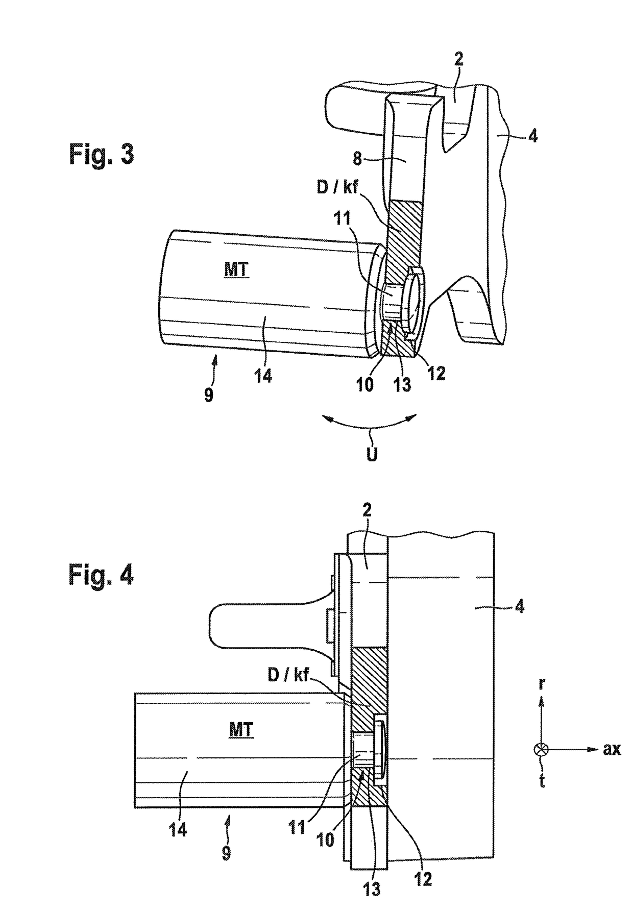
[0015]The forces which occur during braking are therefore transmitted from central portion 3 via limbs 5,6 and hammer head-shaped projections 7,8 radi...


PUM


Abstract

A friction lining or structure of a vehicle disk brake, including an absorption body with a mass MT, with a rear plate including hammer-head-shaped projections and friction material, which is fastened to the rear plate, for bearing against a friction ring, and wherein the projections engage in abutments of receiving recesses in a holder profile for the tangentially fixed holding and the axially displaceable guidance, and therefore introduction of a tangentially directed circumferential force (Fu, friction force) into the holder profile induces a tensile stress in at least one projection. An absorption system for suppressing undesirable vibrations is arranged on the friction lining.

Description

CROSS REFERENCE TO RELATED APPLICATIONS[0001]This application is the U.S. National Phase Application of PCT International Application No. PCT / EP2014 / 075062, filed Nov. 19, 2014, which claims priority to German Patent Application No. 10 2013 223 862.2, filed Nov. 21, 2013 and German Patent Application No. 10 2014 205 232.7, filed Mar. 20, 2014, the contents of such applications being incorporated by reference herein.FIELD OF THE INVENTION[0002]The invention relates to a structure such as in particular a friction lining arrangement for a disk brake.BACKGROUND OF THE INVENTION[0003]In the case of braking operations, vibrations always occur to a certain extent. The vibrations are induced by intermittent frictional engagement between friction material and brake disk into a structure which is stimulated to vibrate. As a function of the prevailing conditions in the individual case, noises resulting from this can arise which are undesirable as a comfort-reducing phenomenon. In addition to t...

Claims


Application Information

Patent Timeline
Patent Type & Authority Patents(United States)
IPC IPC(8): F16D65/00F16D65/092
CPCF16D65/092F16D65/0018
Inventor KUMMEL, KURTKEIL, CHRISTOPHMARSCHNER, HOLGERPIEHLER, CHRISTIANSOCOLOV, SILVIU
Owner CONTINENTAL TEVES AG & CO OHG
Why Eureka
Try Eureka