Piezoelectric sound element

a technology of generating element and piezoelectric, which is applied in the direction of electrical transducers, instruments, deaf-aid sets, etc., can solve the problems of difficult to disperse resonance and make sound pressure frequency characteristics as flat as possibl

Active Publication Date: 2016-07-19
HOKURIKU ELECTRIC INDS +1
View PDF15 Cites 0 Cited by
  • Summary
  • Abstract
  • Description
  • Claims
  • Application Information

AI Technical Summary

Benefits of technology

[0013]The present invention improves a piezoelectric sound generating element having a piezoelectric element and a diaphragm to which the piezoelectric element is affixed, the diaphragm having a fixed outer peripheral portion. In the piezoelectric sound generating element according to the present invention, the diaphragm has a circular profile. The profile of the piezoelectric element is determined such that any portion of the profile of the piezoelectric element is not parallel with the profile of the diaphragm. If a portion of the profile of the piezoelectric element is parallel with a portion of the profile of the diaphragm, the piezoelectric sound generating element has a constant hardness in such portions . If there are a larger number of such portions with a constant hardness, there is a larger difference in amplitude among sound pressures at a plurality of resonance points, which makes it difficult to achieve flat sound pressure frequency characteristics. According to the present invention, the profile of the piezoelectric element is determined such that any portion of the profile of the piezoelectric element is not parallel with the circular profile of the diaphragm, and therefore there are not any portions in which the piezoelectric sound generating element has a constant hardness. Therefore, there is a smaller difference in amplitude among sound pressures at a plurality of resonance points, which makes it easy to achieve flat sound pressure frequency characteristics. As a result, it is possible to generate a sound over a wide frequency range compared to that of the related art.
[0014]Specific examples of the profile of the piezoelectric element according to the present invention include polygonal profiles. Polygonal profiles mean shapes having three or more corner portions. Use of such a piezoelectric element having a polygonal profile for a diaphragm with a circular profile results in the two profiles having no parallel portions. Thus, it is possible to provide a piezoelectric sound generating element that reliably achieves the effect of the present invention by adopting such a configuration.
[0015]The piezoelectric element preferably has an octagonal profile. An octagonal profile is easily obtained by cutting off the corners of a quadrangular profile, and has corner portions with obtuse angles. Therefore, there is a low possibility of separation between the piezoelectric element and the diaphragm at the corner portions of the piezoelectric element. Thus, it is possible to provide a piezoelectric sound generating element with high mechanical strength.
[0016]The piezoelectric element may have a symmetrical or asymmetrical octagonal profile. Adopting an asymmetrical octagonal profile results in flatter sound pressure frequency characteristics due to the asymmetry. The asymmetric octagonal profile may have a pair of long side portions opposing each other, a pair of short side portions opposing each other in a direction orthogonal to the direction in which the pair of long side portions are opposing each other, and four connecting side portions that are shorter than the long side portions and the short side portions and that connect the long side portions and the short side portions. If the piezoelectric element has such a profile, the size of the piezoelectric element can be increased close to a size with which the piezoelectric element is inscribed in a circle. This leads to an increased sound pressure. The pair of long side portions may extend in parallel with each other, and the pair of short side portions may extend in parallel with each other. In this case, the piezoelectric element is easily formed. Alternatively, the pair of long side portions may extend in non-parallel with each other, and the pair of short side portions may extend in parallel with each other. In this case, the pair of long side portions may be shaped to be curved convexly toward the profile of the diaphragm. If the long side portions have such a curved shape, the area of the piezoelectric element can be further increased to increase the sound pressure.
[0017]The four connecting side portions may have a straight shape. This facilitates determination of the shape of the piezoelectric element. In addition, the four connecting side portions may be equal in length, each pair of the connecting side portions opposing each other may be equal in length, or each pair of the connecting side portions opposing each other maybe different in length. In any case, the sound pressure frequency characteristics become flatter as the asymmetry of the piezoelectric element is increased.
[0019]The diaphragm may be formed from an insulating resin film. This makes it easy to obtain a diaphragm with a desired hardness.

Problems solved by technology

Therefore, with such structures according to the related art, it is difficult to disperse resonance and make sound pressure frequency characteristics as flat as possible.

Method used


Image

  • Piezoelectric sound element
  • Piezoelectric sound element
  • Piezoelectric sound element

Examples


Embodiment Construction

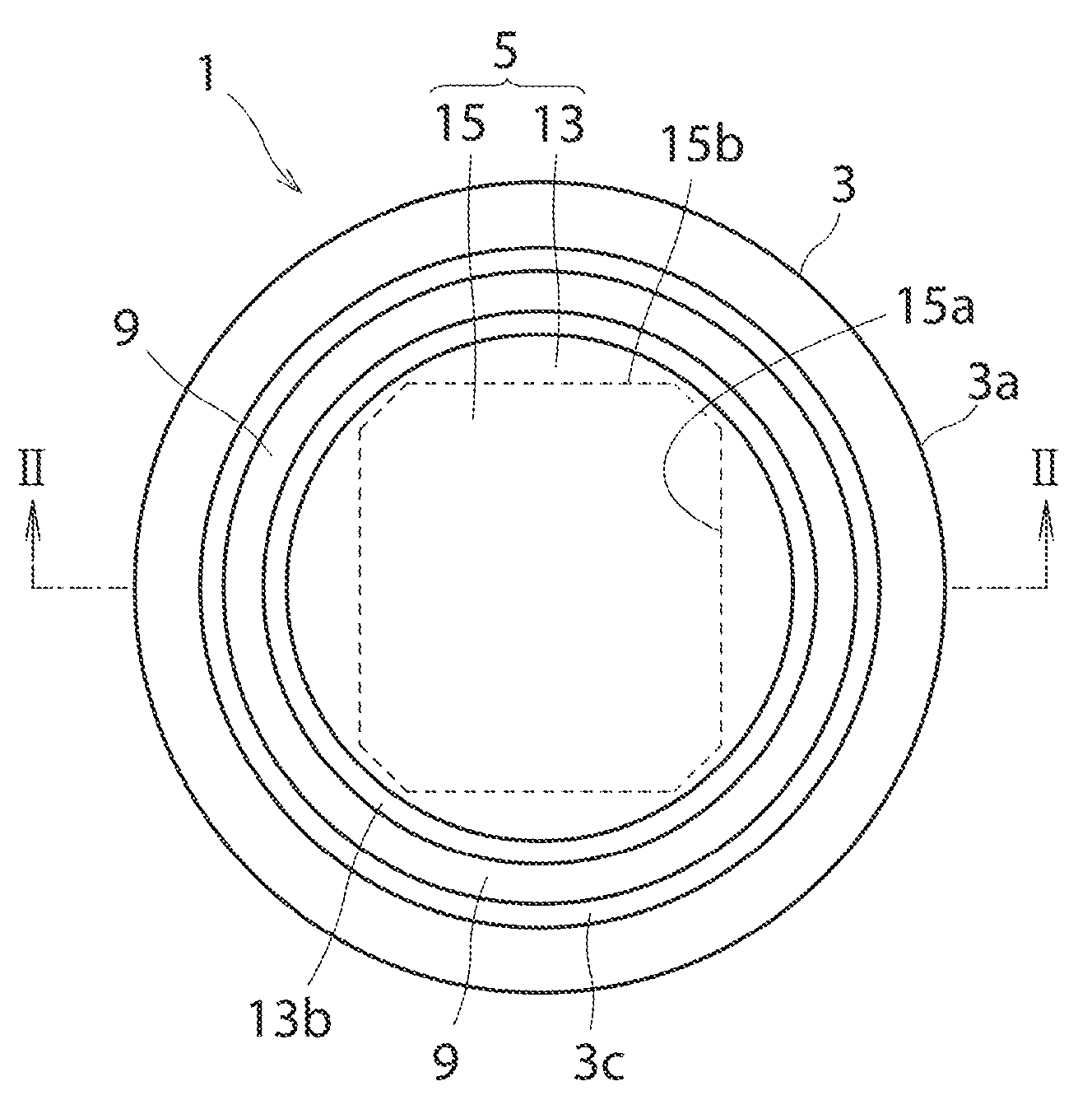
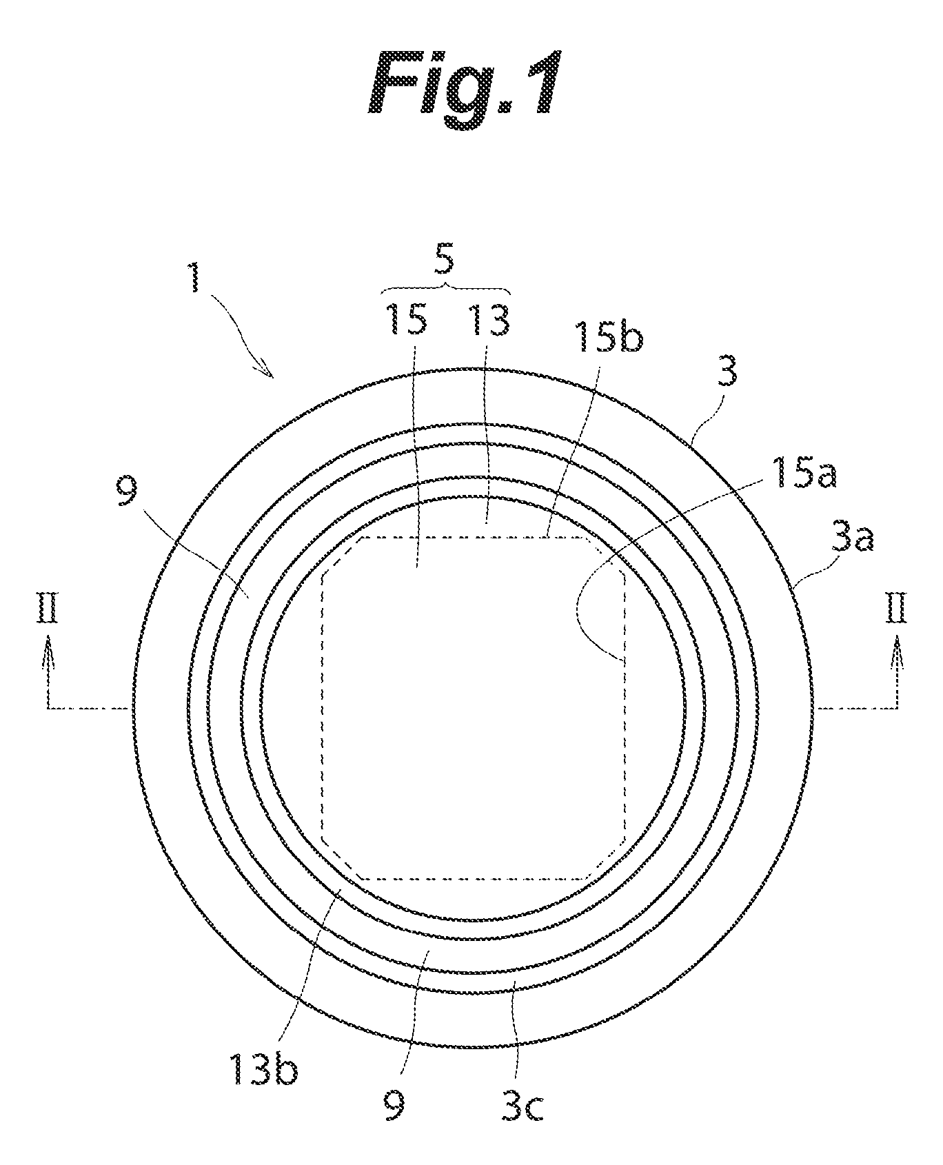
[0025]A piezoelectric sound generating element according to an embodiment of the present invention will be described below with reference to the drawings. FIG. 1 is a plan view of a piezoelectric sound generating device 1 including a piezoelectric sound generating element according to the embodiment. FIG. 2 is a cross-sectional view of the piezoelectric sound generating device 1 illustrated in FIG. 1 taken along line II-II. In the embodiment, in order to facilitate understanding, some components are depicted with exaggeration in terms of thicknesses. The piezoelectric sound generating device 1 illustrated in FIGS. 1 and 2 may be used as a speaker built in a cellular phone, for example. The piezoelectric sound generating device 1 has a base portion 3 and a piezoelectric sound generating element 5 supported by the base portion 3.

[0026]The base portion 3 is constituted from a peripheral wall portion 3a formed in a cylindrical shape, and a bottom wall portion 3b formed in a circular pla...


PUM


Abstract

A piezoelectric sound generating element capable of providing flatter and less fluctuated sound pressure frequency characteristics includes a diaphragm that is formed in a circular plate shape with a circular profile. A piezoelectric element is affixed to the side of a bottom wall portion of the diaphragm. The piezoelectric element has an asymmetric octagonal profile including a pair of long side portions opposing each other, a pair of short side portions opposing each other, and four connecting side portions.

Description

TECHNICAL FIELD[0001]The present invention relates to a piezoelectric sound generating element having a piezoelectric element and a diaphragm to which the piezoelectric element is affixed, the diaphragm having a fixed outer peripheral portion.BACKGROUND ART[0002]FIG. 1 of JP3446685 (Patent Document 1) illustrates the structure of a piezoelectric sound generating element according to the related art in which a diaphragm has a circular profile and a piezoelectric element has a circular profile. In addition, FIG. 7 of Patent Document 1 illustrates the structure of a piezoelectric sound generating element according to the related art in which a diaphragm has a quadrangular profile and a piezoelectric element has a quadrangular profile. In the structure of the piezoelectric sound generating element according to the related art illustrated in FIG. 1 of Patent Document 1, the distance between the profile of the piezoelectric element and the profile of the diaphragm is constant. In the stru...

Claims


Application Information

Patent Timeline
Patent Type & Authority Patents(United States)
IPC IPC(8): H04R25/00G10K9/122H04R17/00
CPCH04R17/00G10K9/122
Inventor SUNAHARA, TADAOTAMURA, MASAHIDEKAWASAKI, OSAMUTSUCHIYA, MASARUSUZUKI, RYUTATSURUTA, MAKOTOMIWA, NOBUHIROSAKAMOTO, HITOSHI
Owner HOKURIKU ELECTRIC INDS
Why Eureka
Try Eureka