
Systems for selectively enabling and disabling hardware features

a technology of hardware components and hardware features, applied in the direction of multi-programming arrangements, instruments, data switching networks, etc., can solve the problems of unreliable hardware features, unstable, undesirable or even unnecessary for certain applications, and the inability to enable all hardware features of the hardware components forming a computer system architectur

Inactive Publication Date: 2016-07-26
INT BUSINESS MASCH CORP
View PDF10 Cites 4 Cited by
  • Summary
  • Abstract
  • Description
  • Claims
  • Application Information

AI Technical Summary

Problems solved by technology

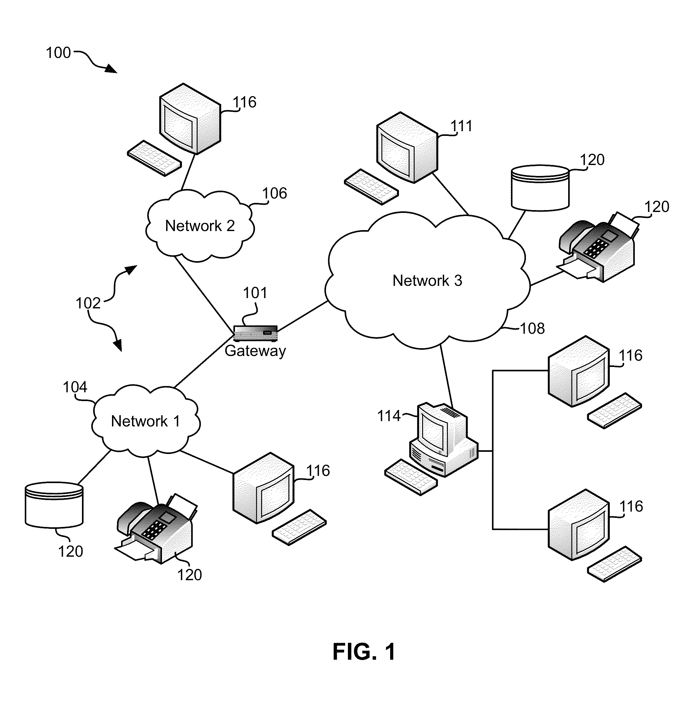
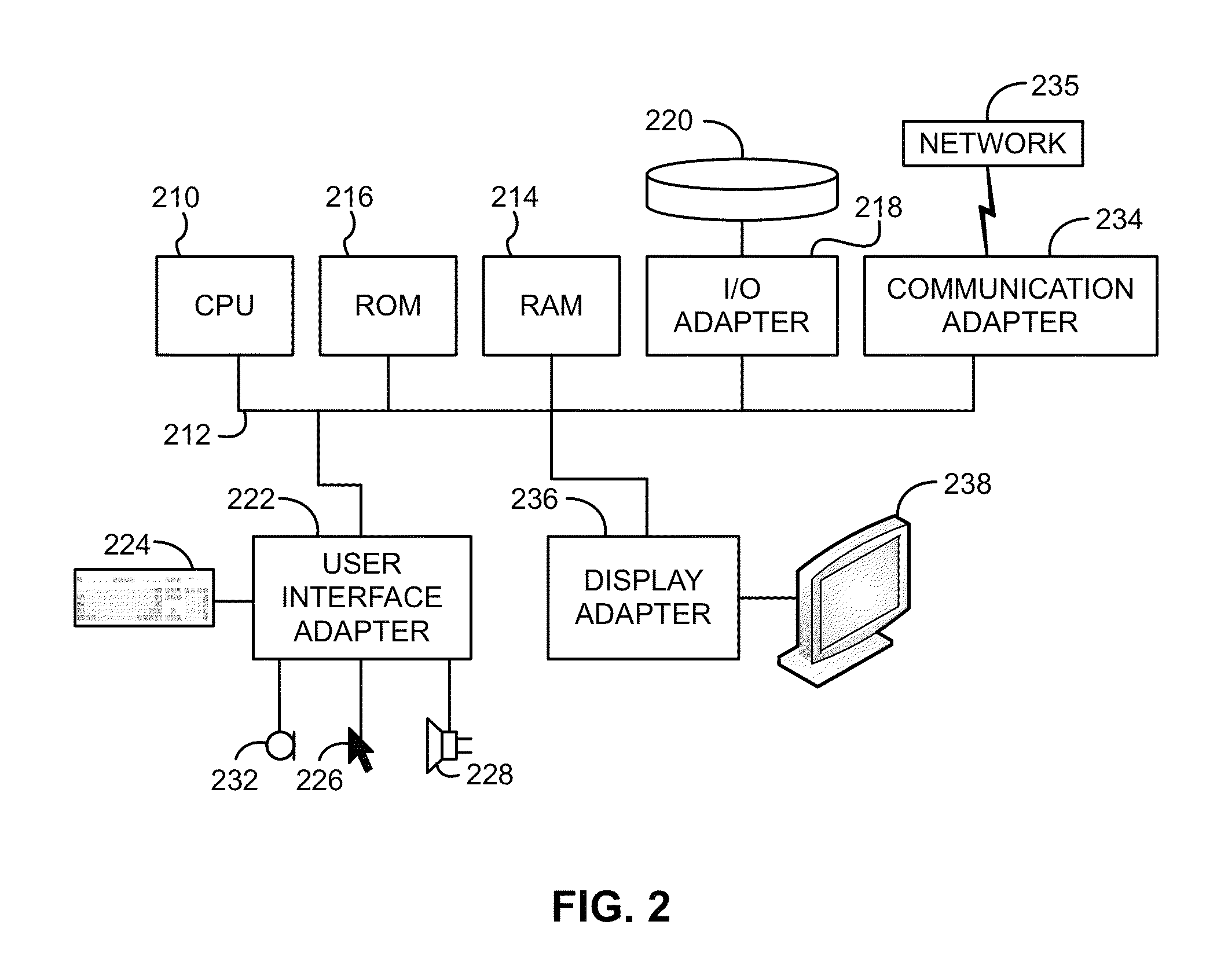
In native IBM computer z / architecture using the IBM z / OS or other IBM operating systems (OSs), I / O operations are complex and require logic to be applied to the data to locate it on storage devices such as direct access storage devices (DASDs), to block and unblock access to the data, and to provide other similar functions via hardware features of hardware components in the computer architecture.
However, in some instances, it may be disadvantageous to enable all hardware features of the hardware components forming a computer system architecture.
For example, hardware features may be characterized as unreliable, unstable, undesirable or even unnecessary for certain applications.
Similarly, software error recovery procedures designed to handle new hardware features may not perform properly, and / or may introduce additional errors impeding the use of particular hardware features.
However, this approach requires the entire system to be taken offline in order to disable even a single hardware feature, resulting in undesirable loss of available resources.
There is no ability to selectively enable or disable individual hardware features for one or more of the hardware components while retaining all remaining functionality available to the computer system architecture.
Alternatively, users may install new microcode to the hardware components in an attempt to address the issue, but this process also requires significant and undesirable downtime while the microcode is installed for the computer system architecture.

Method used


Image

  • Systems for selectively enabling and disabling hardware features
  • Systems for selectively enabling and disabling hardware features
  • Systems for selectively enabling and disabling hardware features

Examples


Embodiment Construction

[0014]The following description is made for the purpose of illustrating the general principles of the present invention and is not meant to limit the inventive concepts claimed herein. Further, particular features described herein can be used in combination with other described features in each of the various possible combinations and permutations.

[0015]Unless otherwise specifically defined herein, all terms are to be given their broadest possible interpretation including meanings implied from the specification as well as meanings understood by those skilled in the art and / or as defined in dictionaries, treatises, etc.

[0016]It must also be noted that, as used in the specification and the appended claims, the singular forms “a,”“an” and “the” include plural referents unless otherwise specified.

[0017]The following description describes methods and systems for controlling the introduction, visibility and / or enabled / disabled state of individual hardware features on systems via a simple ...


PUM


Abstract

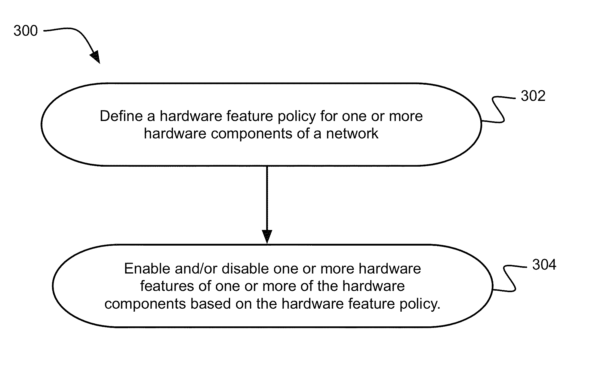
In one embodiment, a system includes a processor and logic integrated with and / or executable by the processor. The logic is adapted to: define a hardware feature policy for one or more hardware components of a system; and enable and / or disable one or more hardware features of one or more of the hardware components based on the hardware feature policy, wherein the hardware feature policy comprises instructions to enable and / or disable access to the one or most hardware features based on one or more criteria selected from a group consisting of: a feature access schedule; a volume feature access group; a job feature access group; and an user feature access group.

Description

BACKGROUND[0001]The present invention relates to management of hardware components in a computer system architecture, and particularly to selectively enabling and disabling hardware features of hardware components in a computer system architecture.[0002]In native IBM computer z / architecture using the IBM z / OS or other IBM operating systems (OSs), I / O operations are complex and require logic to be applied to the data to locate it on storage devices such as direct access storage devices (DASDs), to block and unblock access to the data, and to provide other similar functions via hardware features of hardware components in the computer architecture.[0003]Conventionally, software operating in a computer system architecture exploits all hardware features of various hardware components in the computer system architecture upon the features becoming available. For example, IO Drivers typically build I / O channel programs (a sequence of read and write requests) based on the capabilities of the...

Claims


Application Information

Patent Timeline
Patent Type & Authority Patents(United States)
IPC IPC(8): G06F15/173G06F9/46H04L12/24
CPCG06F9/468H04L41/02G06F13/22G06F13/426G06F8/61G06F9/226H04L65/102G06F9/4411G06F11/2247G06F11/3051G06F11/327
Inventor CANDELARIA, SUSAN K.PAVEZA, JOHN R.
Owner INT BUSINESS MASCH CORP
Learn More