

Connector device
a technology of connecting device and connector, which is applied in the direction of coupling device connection, coupling protective earth/shielding arrangement, electrical apparatus, etc., can solve the problems of increased cost and large use of metal members, and achieve the effect of high electrical contact reliability
- Summary
- Abstract
- Description
- Claims
- Application Information
AI Technical Summary
Benefits of technology
Problems solved by technology
Method used
Image

Examples
Embodiment Construction
[0030]Below, an embodiment of the invention is described with reference to the figures.
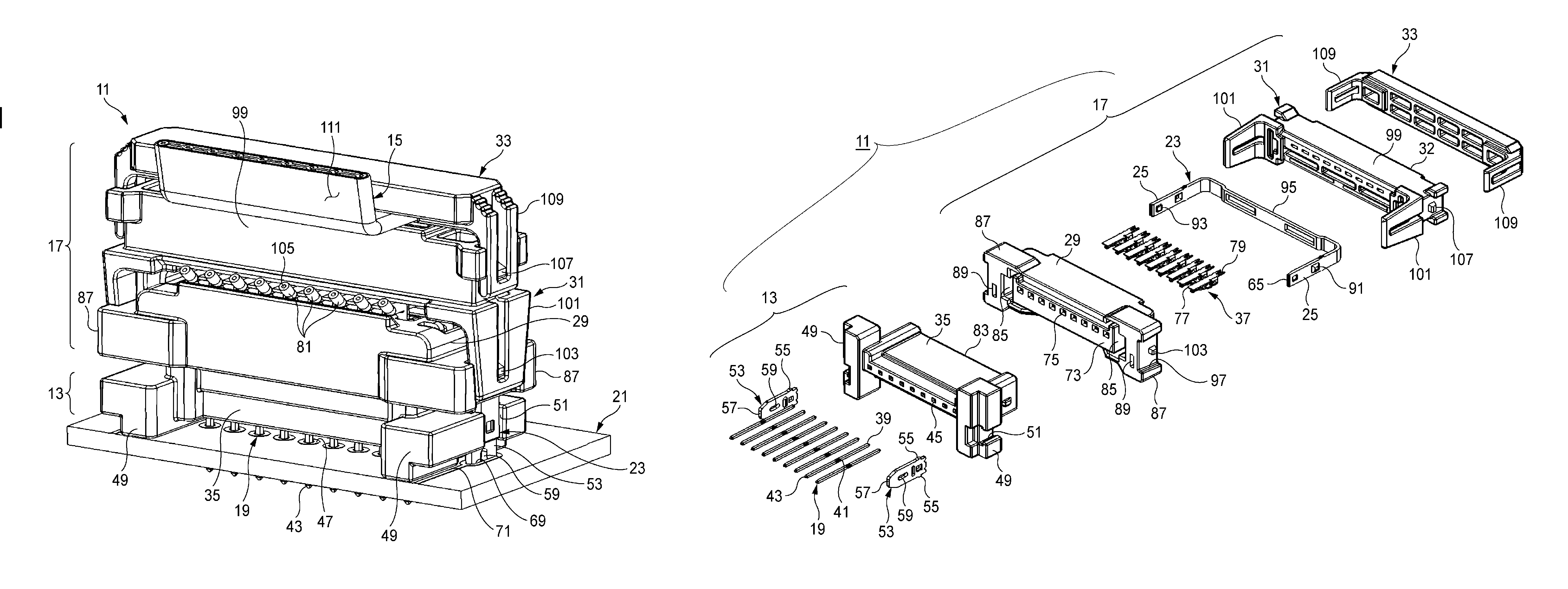
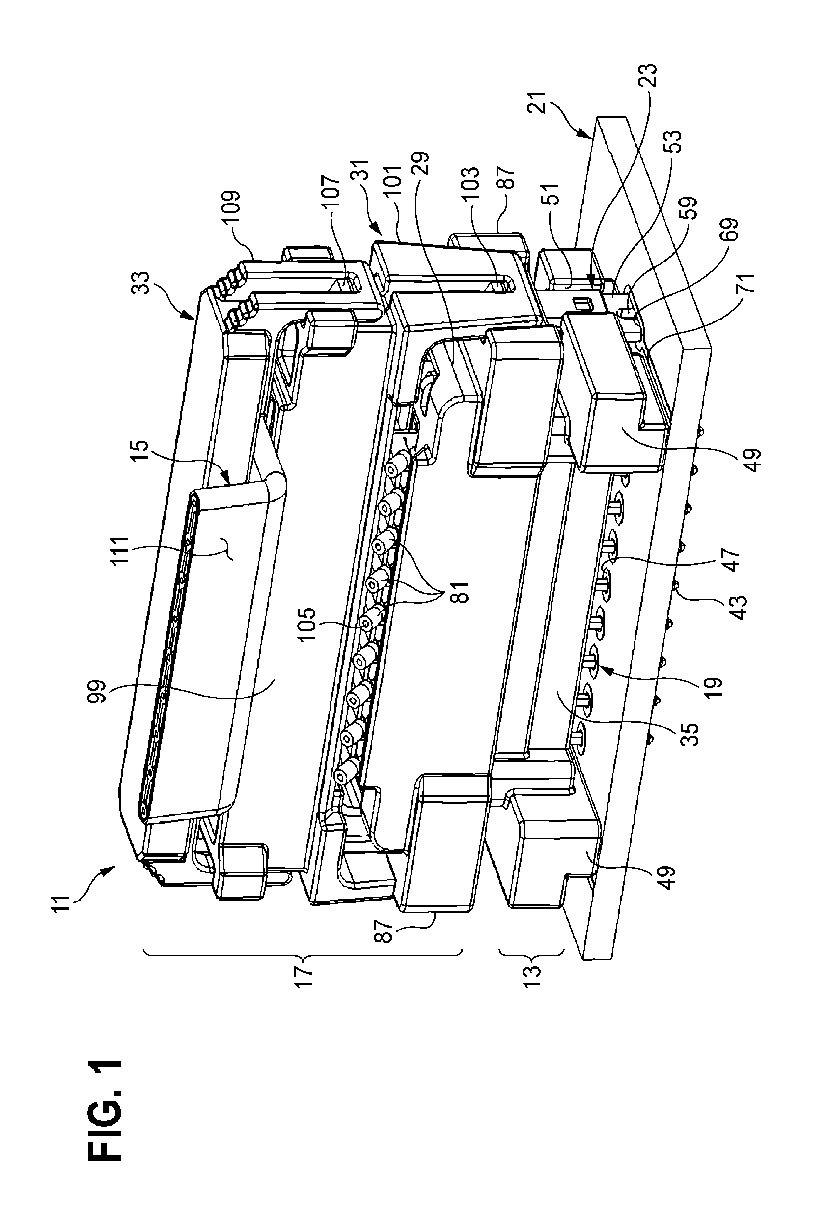
[0031]As shown in FIG. 1, a connector device 11 according to the present embodiment mainly includes a board side connector 13, which is mounted to a circuit board 21 contained in a device such as an ECU (Electronic Control Unit), and an electric wire side connector 17, which is fixed to a shielded electric wire 15 and engaged with the board side connector 13.
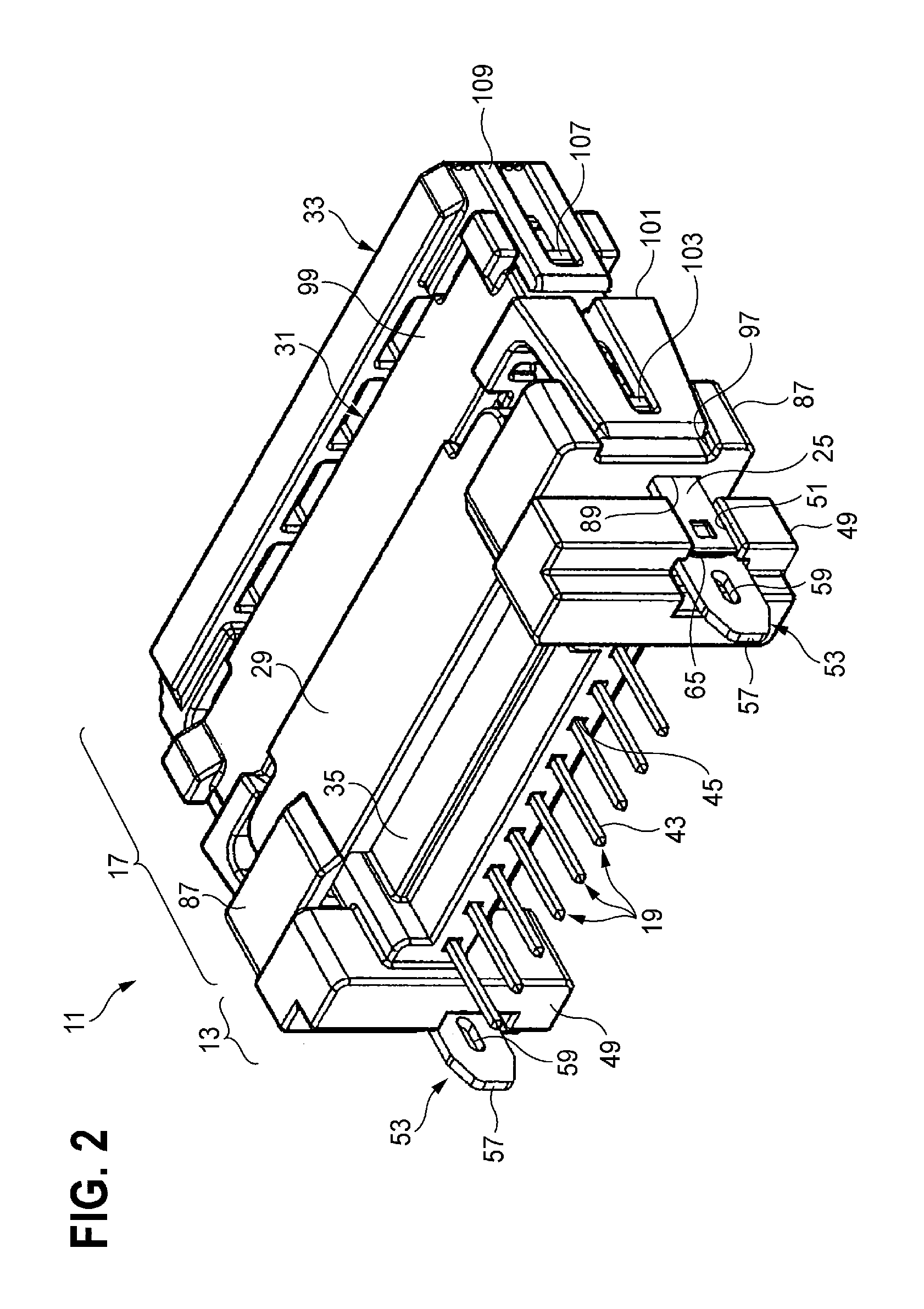
[0032]As shown in FIG. 2, a plurality of board side terminals 19 are derived from the board side connector 13, and soldered to conductors of the circuit board 21. A plurality of members are assembled in the engaging direction to integrally form the electric wire side connector 17 which is engaged to the board side connector 13.
[0033]As shown in FIG. 3, the electric wire side connector 17 which is separated from the board side connector 13, has a bus bar plate 23, parts of which (U-shaped two ends projecting pieces 25 to be described) project f...
PUM
 Abstract
Description
Claims
Application Information