Power supply unit testing system

a power supply unit and testing system technology, applied in power supply testing, fault location by increasing the damage at fault, instruments, etc., can solve the problem of inefficient manual adjustment of the resistance value of the electric load

Inactive Publication Date: 2016-08-02
SCIENBIZIP CONSULTINGSHENZHENCO
View PDF9 Cites 0 Cited by
  • Summary
  • Abstract
  • Description
  • Claims
  • Application Information

AI Technical Summary

Benefits of technology

[0005]In order to provide users with qualified PSUS, the PSUS should pass OCP test. In typical OCP test systems, each PSU is connected to an electric load. The electric load has a knob to adjust a resistance value of the electric load. An operator should operate the knob to steadily decrease resistance of the load, thus increasing current flowing to the load. However, it's inefficient to adjust the resistance value of the electric load manually.

Problems solved by technology

However, it's inefficient to adjust the resistance value of the electric load manually.

Method used


Image

  • Power supply unit testing system
  • Power supply unit testing system
  • Power supply unit testing system

Examples


Embodiment Construction

[0010]The disclosure is illustrated by way of example and not by way of limitation. In the figures of the accompanying drawings, like references indicate similar elements. It should be noted that references to “an” or “one” embodiment in this disclosure are not necessarily to the same embodiment, and such references mean “at least one.”

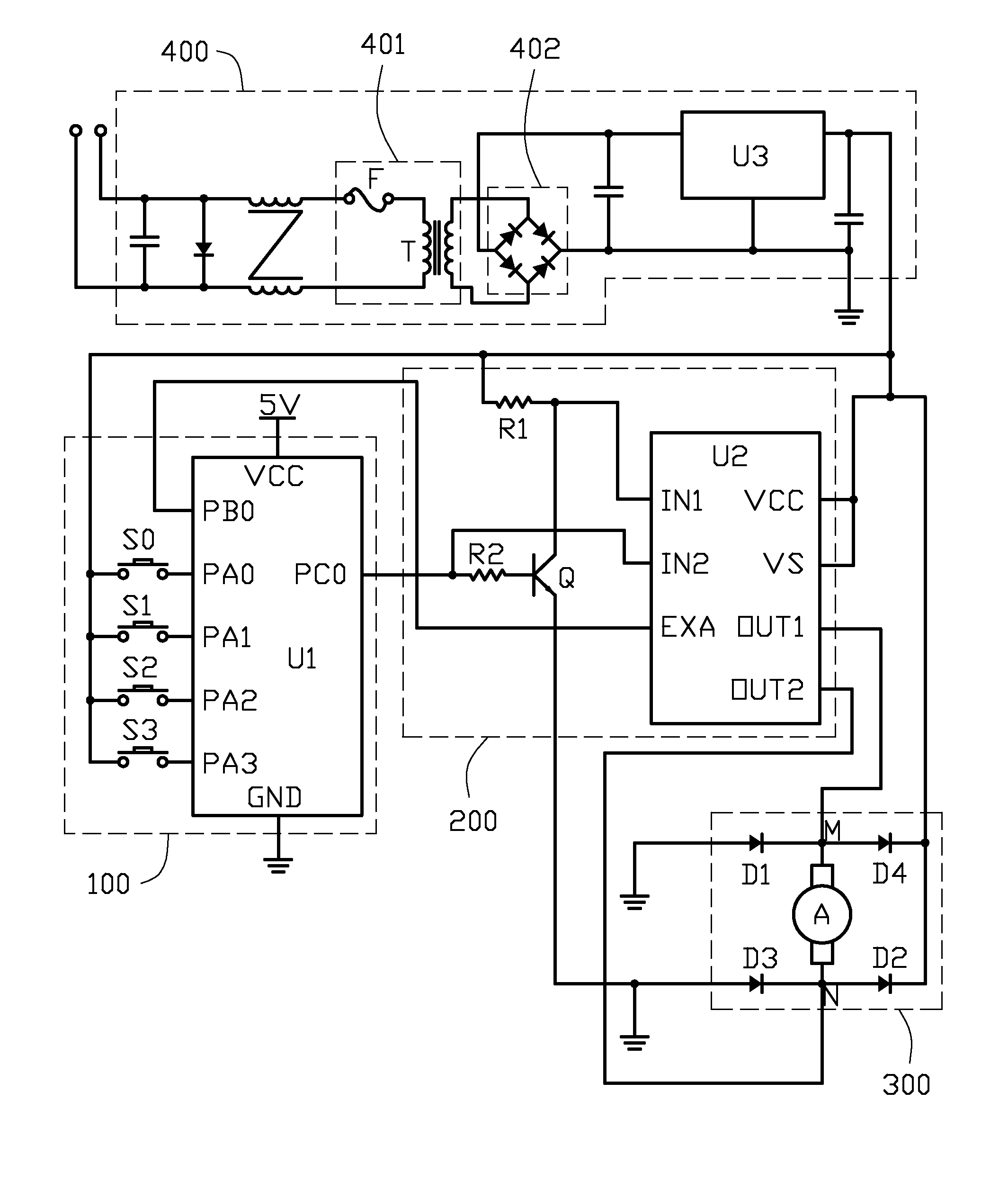
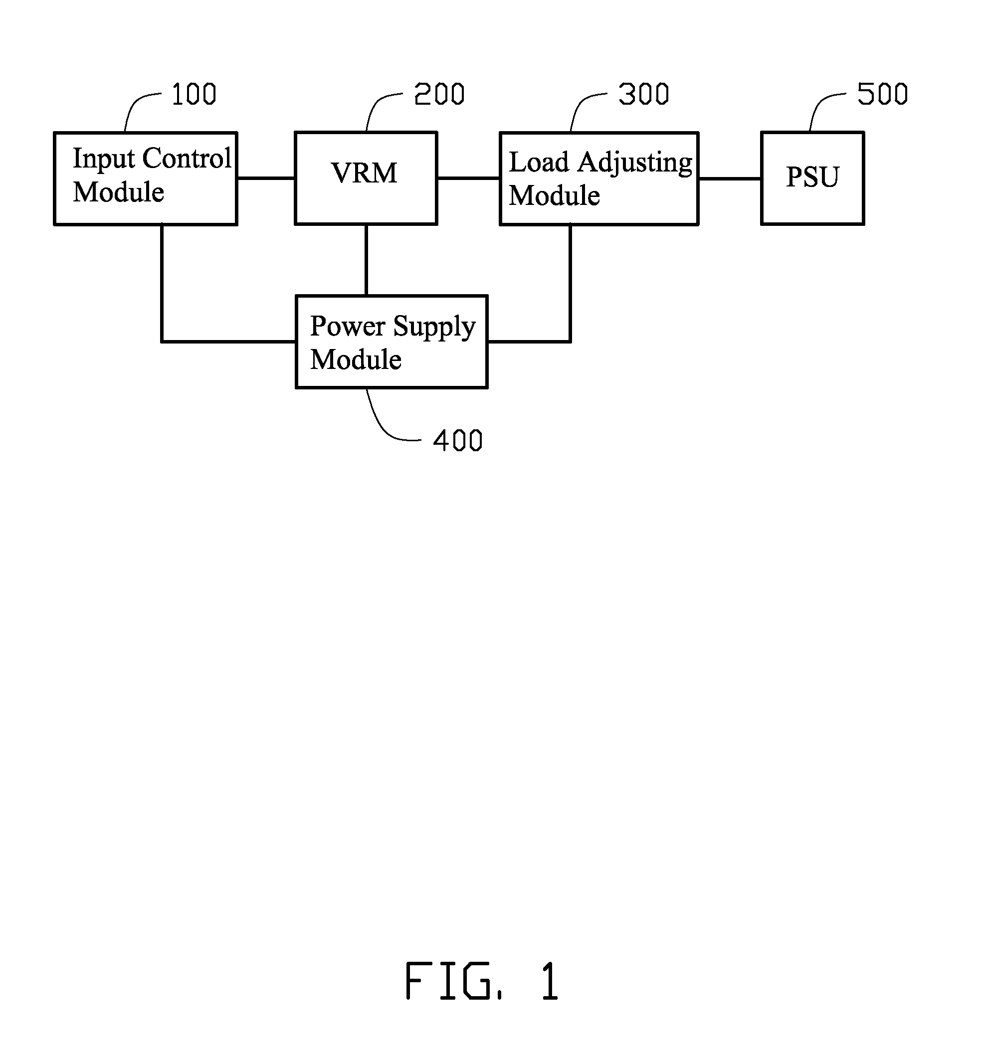
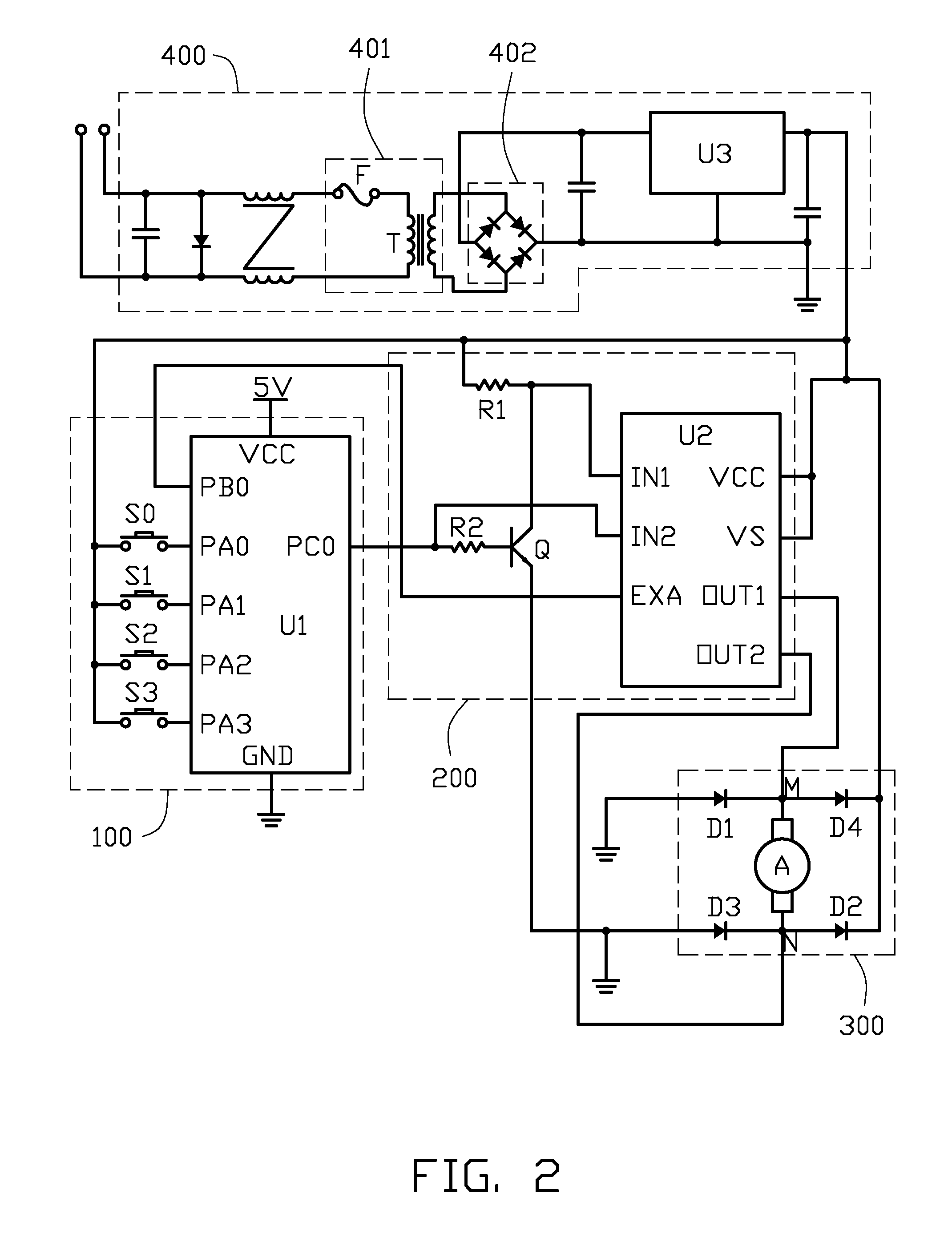
[0011]FIG. 1 shows that an embodiment of a testing system is configured to perform an OCP test on a power supply unit (PSU) 500. The testing system includes an input control module 100, a voltage regulation module (VRM) 200, a load adjusting module 300, and a power supply module 400. The power supply module is configured to supply working voltages to the input control module 100, the VRM 200, and the load adjusting module 300. The input control module 100 is configured to receive input signals and control an output voltage of the VRM 200 according to the input signals. The load adjusting module 300 includes a rotating means which rotates under the out...


PUM


Abstract

A system for testing a PSU includes an input control module, a voltage regulating module, and a load adjusting module. The input control module includes a microcontroller and a plurality of key switches connected to the microcontroller. The microcontroller is configured to receive input instruction from the plurality of key switches and output a control signal according to the input instruction. The voltage regulating module is configured to receive the control signal and generate an output voltage with a voltage value associated with the control signal. The load adjusting module includes a motor coupled to the output voltage of the voltage regulating module. The motor is rotatable in opposite direction to adjust an output current of the PSU. A rotating speed of the motor is in direct proportion to the voltage value of the output voltage.

Description

BACKGROUND[0001]1. Technical Field[0002]The present disclosure relates to a power supply unit (PSU) testing system.[0003]2. Description of Related Art[0004]Many personal computers utilize a PSU for providing direct current (DC) power sources (e.g., 3V, 5V, 12V, etc.) to components thereof. The PSU usually has an over current protection (OCP) function to detect whether an output current to each of the components exceeds a preset tolerance value. If the output current exceeds the preset tolerance value, the PSU is automatically powered off to protect the components.[0005]In order to provide users with qualified PSUS, the PSUS should pass OCP test. In typical OCP test systems, each PSU is connected to an electric load. The electric load has a knob to adjust a resistance value of the electric load. An operator should operate the knob to steadily decrease resistance of the load, thus increasing current flowing to the load. However, it's inefficient to adjust the resistance value of the e...

Claims


Application Information

Patent Timeline
Patent Type & Authority Patents(United States)
IPC IPC(8): G01R31/00G01R31/40G01R31/319
CPCG01R31/40G01R31/31924
Inventor GAO, ZHI-YONGLIU, YU-LIN
Owner SCIENBIZIP CONSULTINGSHENZHENCO
Why Eureka
Try Eureka