A hydrogen-oxygen fuel cell bipolar plate intake structure and its fuel cell

A fuel cell and air intake structure technology, applied in the direction of fuel cells, fuel cell parts, battery electrodes, etc., can solve the problems of reducing the effective utilization of bipolar plate area, unfavorable fuel carrying, narrowing of flow channels, etc., to achieve Solve the problem of uniform distribution and carrying, improve the utilization rate of area, and reduce the effect of carrying resistance

Active Publication Date: 2020-11-27
CEMT CO LTD
View PDF4 Cites 0 Cited by
  • Summary
  • Abstract
  • Description
  • Claims
  • Application Information

AI Technical Summary

Problems solved by technology

[0004] First, the flow channel structure on the fuel cell plate directly affects the distribution and carrying capacity of the fuel, and determines the fuel cell production capacity. However, the existing fuel cell plate flow channels use intricate flow channels to improve the fuel distribution. The mechanism is complex, the manufacturing process is difficult, and this complex flow path is not conducive to the delivery of fuel
[0005] Second, for the discharge of fuel cell products (water), the use of complex-structured flow channels will inevitably narrow the flow channels, and the water generated by the reaction will easily block the flow channels, resulting in interruption of fuel supply and resulting in failure of the fuel cell to work normally.
[0006] Third, the traditional misplacement design of the seals of the hydrogen and oxygen plates, due to the dislocation of the sealing glue line, the sealing is difficult, and the use of this dislocation requires more space, which reduces the effective use of the area of ​​the bipolar plate Rate
[0007] Fourth, when the fuel is reacting, due to the limited length of the flow channel, a large part of the fuel will be discharged before participating in the reaction in the future, resulting in a large amount of fuel recovery, which is not conducive to the energy conversion of fuel

Method used


Image

  • A hydrogen-oxygen fuel cell bipolar plate intake structure and its fuel cell
  • A hydrogen-oxygen fuel cell bipolar plate intake structure and its fuel cell
  • A hydrogen-oxygen fuel cell bipolar plate intake structure and its fuel cell

Examples


Embodiment Construction

[0039] Below in conjunction with specific embodiment, further illustrate the present invention. These examples are only for illustrating the present invention and are not intended to limit the scope of the present invention. In the description of the present invention, it should be noted that unless otherwise specified and limited, the terms "installation", "installation" and "connection" should be interpreted in a broad sense, for example, it can be a fixed connection or an optional connection. Detachable connection, or integral connection; it can be mechanical connection or electrical connection; it can be direct connection or indirect connection through an intermediary, and it can be the internal communication of two components. Those of ordinary skill in the art can understand the specific meanings of the above terms in the present invention in specific situations.

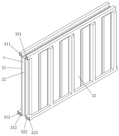
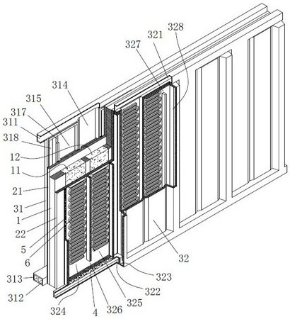
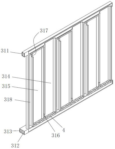
[0040] Now in conjunction with the accompanying drawings, the structural features of the present invention...


PUM


Abstract

The invention discloses a hydrogen-oxygen fuel cell bipolar plate intake structure, relates to the technical field of fuel cells, and includes an oxygen zone flow field plate and a hydrogen zone flow field plate, and the top of the oxygen zone flow field plate is penetrated with a Oxygen uniform distribution channel, the bottom penetrating type is equipped with oxygen area drainage channel and residual oxygen flow channel, the top penetrating type of hydrogen area flow field plate is provided with hydrogen uniform distribution channel, and the bottom penetrating type is equipped with hydrogen area drainage channel and residual hydrogen flow channel; the flow field plate in the oxygen area is provided with a plurality of oxygen reaction flow areas in a straight waterfall structure; the flow field plate in the hydrogen area is provided with a plurality of oxygen reaction flow areas in a straight waterfall structure. Corresponding hydrogen reacting flow zone. The present invention also proposes a fuel cell assembled using the intake structure of the hydrogen-oxygen fuel cell bipolar plate. The present invention has a simple structure and is easy to produce and process. It is beneficial to improve the conversion rate of fuel.

Description

technical field [0001] The invention belongs to the technical field of fuel cells, and in particular relates to a hydrogen-oxygen fuel cell bipolar plate intake structure and a fuel cell thereof. Background technique [0002] With the increasing consumption of non-renewable energy and the continuous deterioration of the environment, it is inevitable to find renewable new energy to replace non-renewable energy. Among them, fuel cell is one of the representatives of new energy and a promising new power source. , generally use hydrogen, carbon, methanol, borohydride, coal gas or natural gas as the fuel, as the negative electrode, and use oxygen in the air as the positive electrode, which has a good market prospect. [0003] However, hydrogen-oxygen fuel cells currently have the following problems: [0004] First, the flow channel structure on the fuel cell plate directly affects the distribution and carrying capacity of the fuel, and determines the fuel cell production capacit...

Claims


Application Information

Patent Timeline
Patent Type & Authority Patents(China)
IPC IPC(8): H01M8/026H01M8/0276H01M8/22H01M4/92
CPCH01M4/92H01M8/026H01M8/0276H01M8/22Y02E60/50Y02P70/50
Inventor 徐黎明宋书范龚靖
Owner CEMT CO LTD
Why Eureka
Try Eureka