Clot removal system and method

a clot and clot technology, applied in the field of clot removal system, can solve the problems of obstructing critical blood flow, affecting the life of patients, and damage to tissues,

Active Publication Date: 2016-08-09
COOK MEDICAL TECH LLC
View PDF17 Cites 18 Cited by
  • Summary
  • Abstract
  • Description
  • Claims
  • Application Information

AI Technical Summary

Problems solved by technology

This partially or completely blocked blood flow may prevent normal blood flow and oxygen from reaching certain tissues and, thus, may result in damage to the tissues.
If a clot becomes dislodged from the vessel walls it may travel to other portions of the vascular system, where it may ultimately occlude critical blood flow.
Regardless of the particular location of the clot within the vascular system, clots consisting of blood or other substances, if left untreated, may cause serious damage and, in some cases, may become life threatening.
A number of risks are associated with clot removal procedures, including risks associated with the use of thrombolytic agents and risks associated with the migration of dislodged portions of the clot.

Method used


Image

  • Clot removal system and method
  • Clot removal system and method
  • Clot removal system and method

Examples


Embodiment Construction

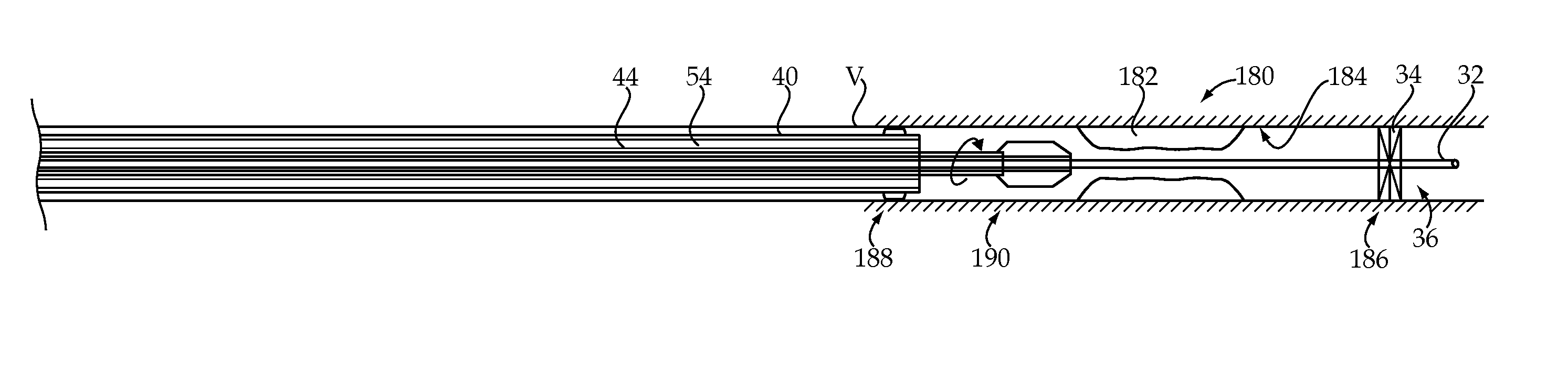
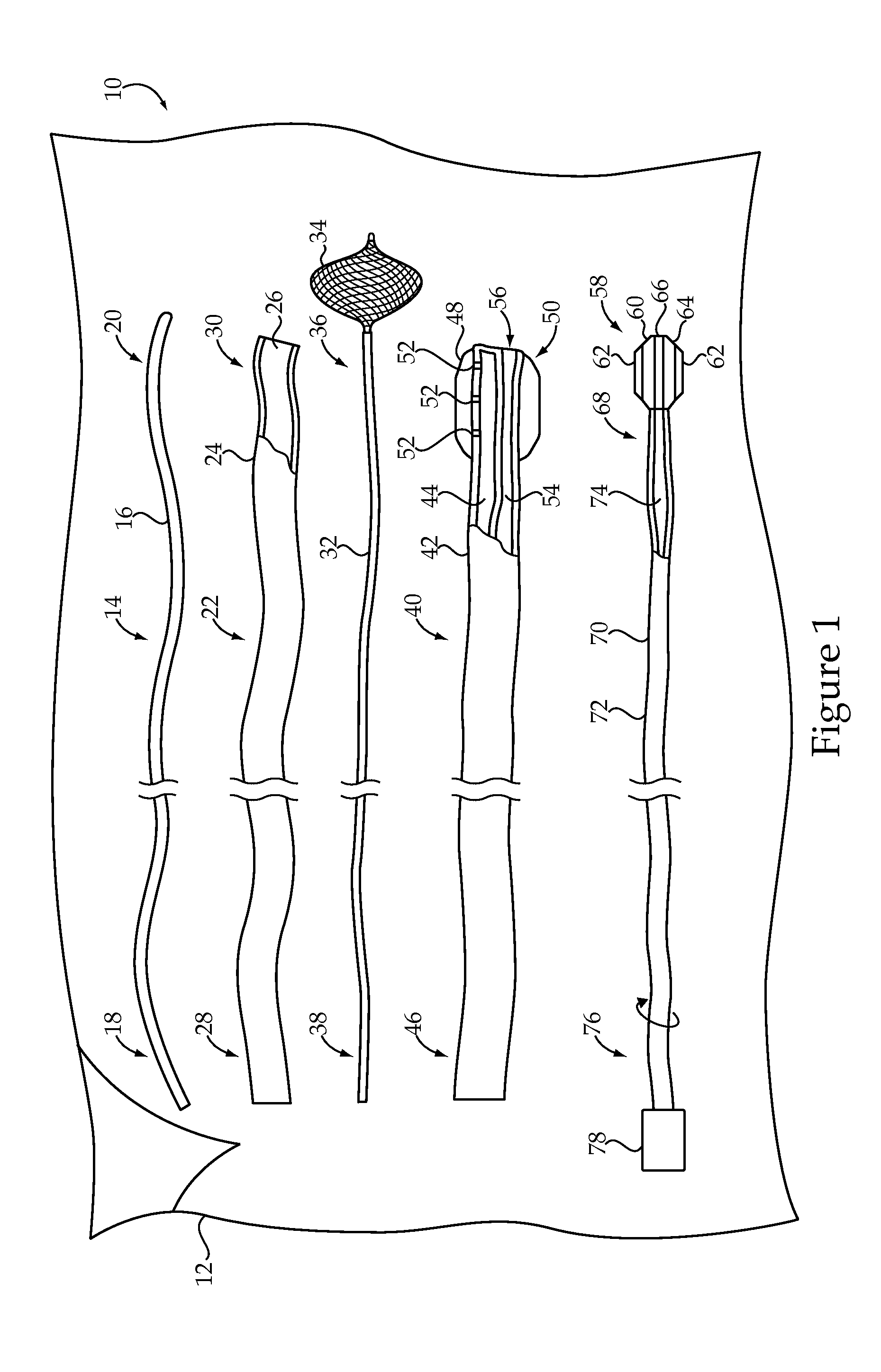
[0022]Referring to FIG. 1, there is shown a clot removal system 10 according to one embodiment of the present disclosure. The clot removal system 10 may include a number of components, which may be provided within a sterile, tear open package 12, as is known in the art. In performing a clot removal procedure on a patient, some or all of the components of the clot removal system 10 may be used, depending upon the specifics of the procedure to be performed. As should be appreciated, however, the components shown in FIG. 1 might be separately packaged and / or the clot removal system 10 might also include components in addition to those shown, including components routinely used in percutaneous vascular procedures.

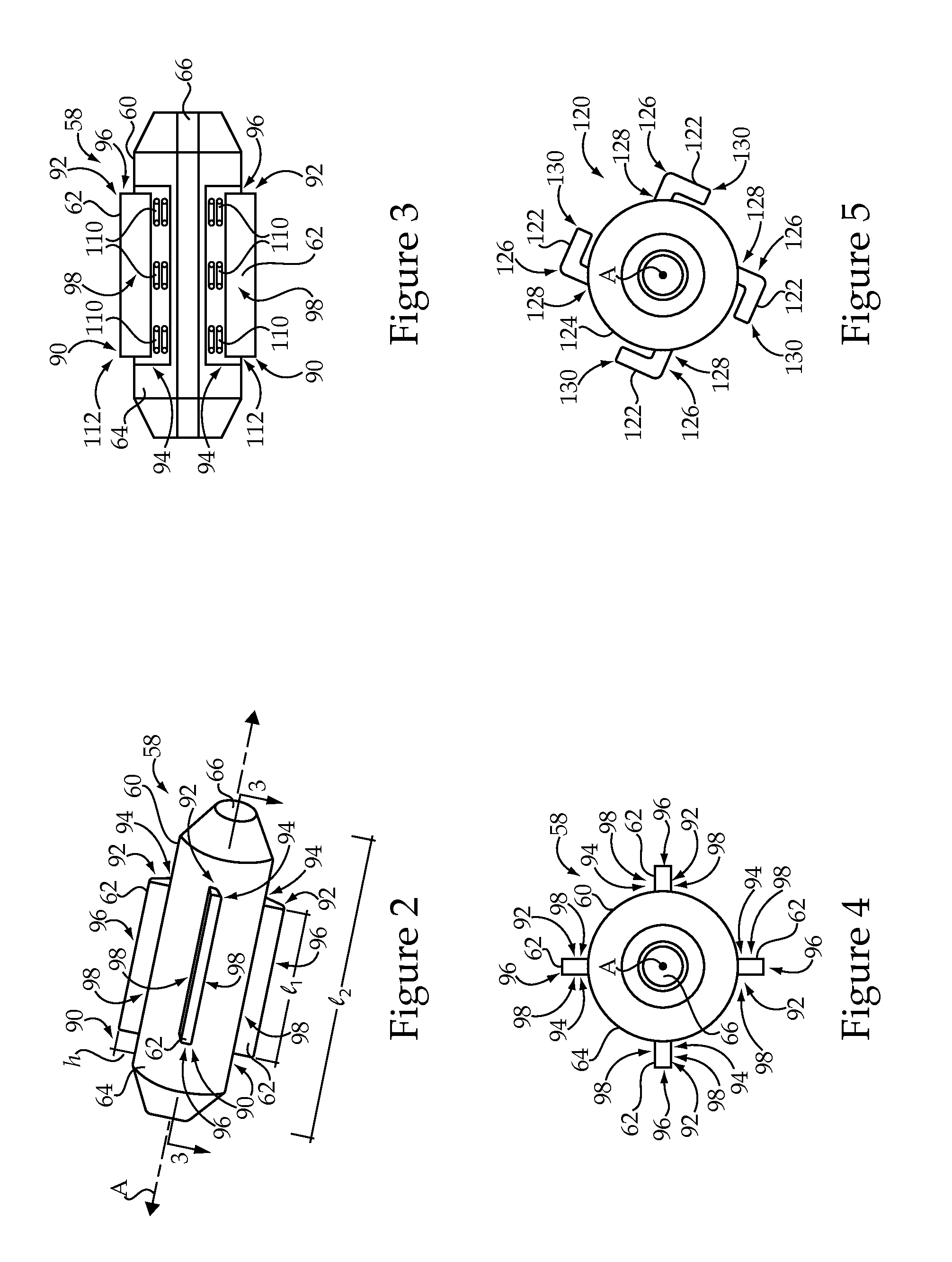
[0023]The clot removal system 10 may include at least one wire guide 14, which is a device commonly used in vascular procedures to introduce a wide variety of medical devices into the vascular system. Generally speaking, wire guide 14 includes an elongate flexible body 16 exten...


PUM


Abstract

A clot removal system includes first and second barriers that each have an expanded configuration forming an occlusion within a vessel and a collapsed configuration. At least one deployment device distally deploys the first barrier relative to a clot, and proximally deploys the second barrier relative to the clot. The at least one deployment device also delivers a thrombolytic agent into an isolated segment defined at least in part by the first and second barriers in the expanded configurations, and positions an impeller within the isolated segment. The impeller includes a substantially cylindrical hub having at least two impeller blades attached to rotate with the cylindrical hub. Each of the at least two impeller blades has a proximal end attached to the cylindrical hub and a distal end attached to the cylindrical hub. The impeller has a transport configuration in which the at least two impeller blades are moved toward the cylindrical hub and a deployed configuration in which the at least two impeller blades are moved away from the cylindrical hub.

Description

RELATION TO OTHER PATENT APPLICATION[0001]This application claims priority to provisional patent application 61 / 552,535, filed Oct. 28, 2011, with the same title.TECHNICAL FIELD[0002]The present disclosure relates generally to a clot removal system, and more particularly to a clot removal system including at least one deployment device deploying first and second barriers, a thrombolytic agent, and an impeller including a cylindrical hub having at least two impeller blades.BACKGROUND[0003]Thrombosis is the formation of a thrombus, or blood clot, within the vascular system of a patient. A blood clot typically occurs when blood hardens from a liquid to a solid. When attached to vessel walls, blood clots, and other substances, such as plaque or fat, may reduce or block blood flow downstream from the clot. This partially or completely blocked blood flow may prevent normal blood flow and oxygen from reaching certain tissues and, thus, may result in damage to the tissues. If a clot becomes...

Claims


Application Information

Patent Timeline
Patent Type & Authority Patents(United States)
IPC IPC(8): A61B17/3207A61M25/10A61F2/01A61B17/22A61B17/221
CPCA61B17/320758A61B17/320725A61B17/320783A61M2025/109A61F2/013A61B2017/22051A61B2017/22054A61B2017/2212
Inventor TEKULVE, KURT
Owner COOK MEDICAL TECH LLC
Why Eureka
Try Eureka