Guide frame support device

a support device and frame technology, applied in the direction of auxillary welding devices, soldering devices, manufacturing tools, etc., can solve the problems of pipe damage, achieve the effect of improving welding process efficiency, strong elasticity, and easy adjustmen

Active Publication Date: 2016-08-09
HYUNDAI HEAVY IND CO LTD
View PDF35 Cites 2 Cited by
  • Summary
  • Abstract
  • Description
  • Claims
  • Application Information

AI Technical Summary

Benefits of technology

[0016]According to the present invention, when there is a need to minutely adjust a separation distance between a guide frame and a pipe during a welding process, by using a torsion spring that can be easily adjusted by a worker and has strong elasticity compared to a plate spring, a guide frame support device can be installed in a lesser number of guide frame devices can be installed, and elasticity can be freely adjusted, thereby enabling the efficiency of a welding process to be improved.

Problems solved by technology

When a slight error occurs upon adjusting the separation distance, a part of the multiple guide frame support devices 10 installed in a circumferential direction of the pipe may not come into contact with a surface of the pipe, or the pipe may be damaged by the guide frame support devices being excessively touched due to unskilled adjustment.
Also, when an external diameter of the pipe is changed in size, it is problematic in that a plurality of insert type plates for adjusting the separation distance must be inserted in order to reduce or extend the separation distance, and it is also problematic in that many guide frame support devices 10 must be attached in a circumferential direction of the guide frame G in order to maintain regular bearing power because an elastic limit of the double plate-spring is weak.

Method used


Image

  • Guide frame support device
  • Guide frame support device
  • Guide frame support device

Examples


Embodiment Construction

[0020]Hereinafter, embodiments of the present invention will be described in detail with reference to the accompanying drawings. It should be understood that a size or shape of the elements illustrated in the drawings may be exaggeratedly drawn to more clearly and conveniently explain the present invention. Furthermore, the terms specifically defined in consideration of the configuration and operation of the present invention may be changed depending on the intention or practice of a user and an operator. The terms should be defined based on all contents in the specification. The present invention may be embodied in different forms and should not be construed as limited to the embodiments set forth herein. Those having ordinary skill in the art who understand the present invention could easily embody different embodiments which belong to the scope of the present invention.

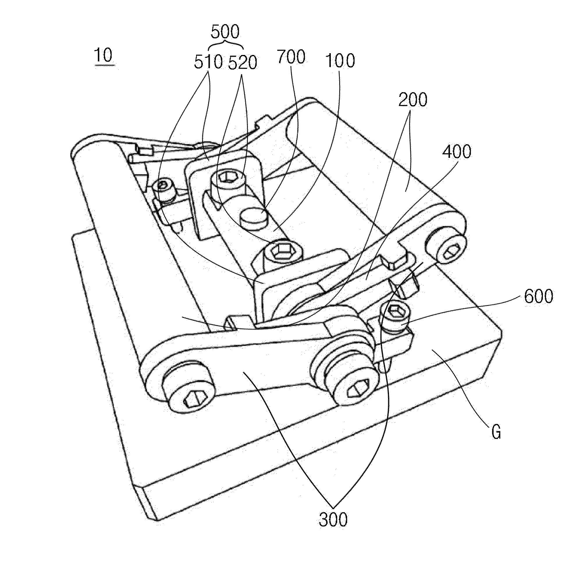
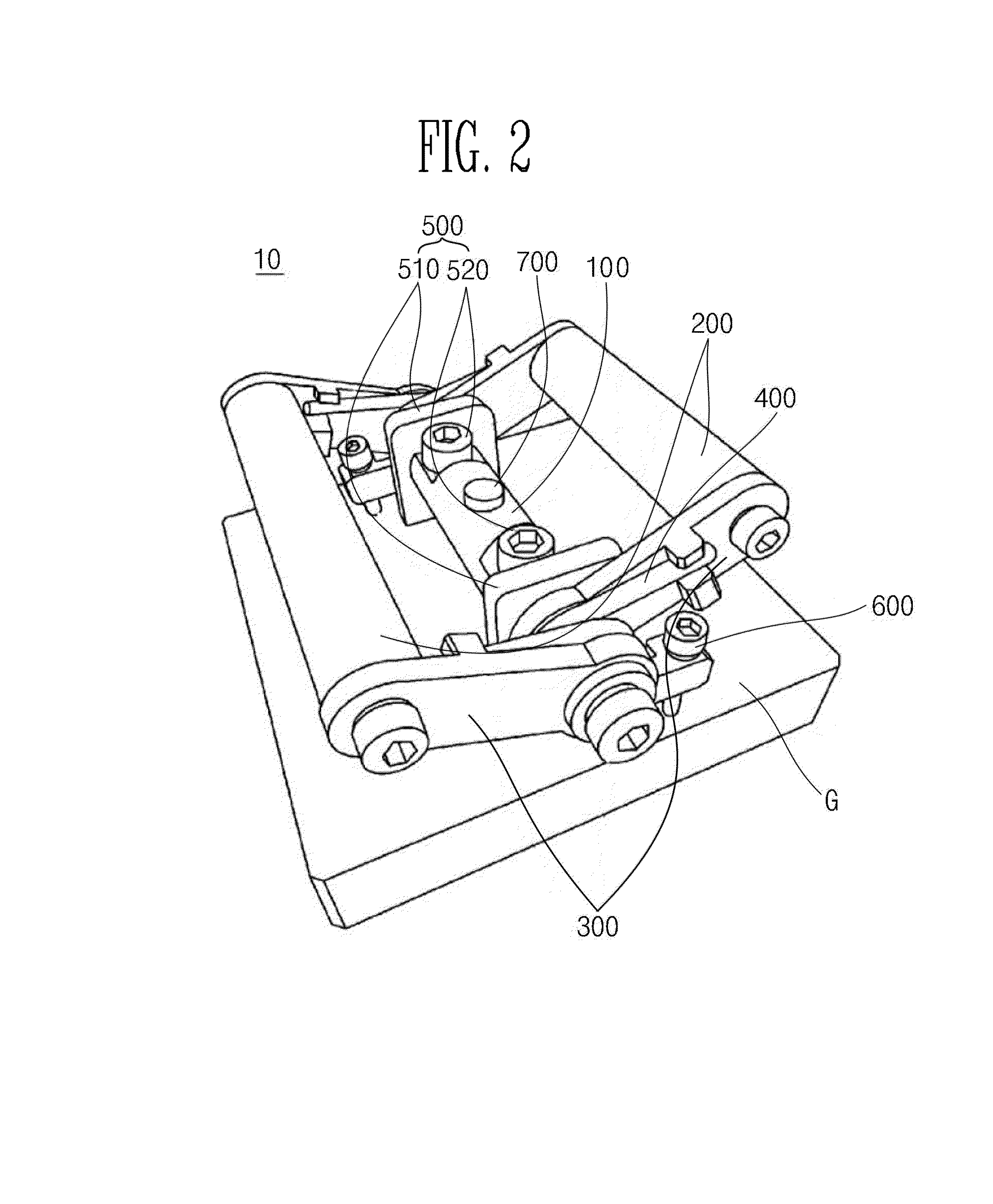
[0021]As illustrated in FIG. 2, a guide frame support device 10 according to an embodiment of the present invent...


PUM

PropertyMeasurementUnit
elastic forceaaaaaaaaaa
separation distanceaaaaaaaaaa
elasticityaaaaaaaaaa

Abstract

Provided is a guide frame support device for a pipe welding device, the guide frame support device, which supports a guide frame provided on an outer circumferential surface of a pipe to be welded, including: a hinge bar connected to an inner circumferential surface of the guide frame; a pair of support bars which rotates around the hinge bar at a predetermined angle; hinge links, one side of each of which is hinge-connected to both ends of the hinge bar and the other side of each of which is connected to both ends of the pair of support bars; and a torsion spring provided between the pair of support bars and for providing elastic force to enable the support bars to rotate around the hinge bar at a predetermined angle.

Description

CROSS-REFERENCE TO RELATED APPLICATIONS[0001]This application is the U.S. national stage application of International Patent Application No. PCT / KR2012 / 004744, filed Jun. 15, 2012, which claims priority to Korean Application No. 10-2012-0005625, filed Jan. 18, 2012, the disclosures of each of which are incorporated herein by reference in their entirety.TECHNICAL FIELD[0002]The present invention relates to a guide frame support device, and more specifically, to a guide frame support device which enables pipe working efficiency to be improved.BACKGROUND ART[0003]In general, when a pipe is welded using a welding device, a guide frame in a circular shape is installed on an outer circumferential surface of the pipe, and a welding portion of the pipe is welded by the welding device which is rotated along the guide frame.[0004]At this time, a separation distance between the guide frame and the outer circumferential surface of the pipe must be regular in order to perform accurate and rapid ...

Claims


Application Information

Patent Timeline
Patent Type & Authority Patents(United States)
IPC IPC(8): B23K1/00B23K37/02B23K37/053
CPCB23K37/0276B23K37/0533B23K37/0217B23K2201/10B23K2101/10B23K37/00
Inventor KIM, JONG JUNKIM, JONG CHEOLMOON, HYEONG SOON
Owner HYUNDAI HEAVY IND CO LTD
Why Eureka
Try Eureka