
Capillary metering device and method for operating such a capillary metering device

a capillary metering and capillary metering technology, which is applied in the direction of liquid transfer devices, instruments, packaged goods types, etc., can solve the problems of unambiguous adhesion properties, unambiguous self-holding action upon standstill of the vibration body, and unambiguous flow properties, so as to facilitate the flowability in the vibrating state, facilitate the flow process of powder, and precisely switch off the powder flow

Active Publication Date: 2016-08-09
HARRO HOFLIGER VERPACKUNGSMASCHEN
View PDF8 Cites 11 Cited by
  • Summary
  • Abstract
  • Description
  • Claims
  • Application Information

AI Technical Summary

Benefits of technology

[0007]The invention furthermore has the object to provide a method for metering a powder product by means of such a capillary metering device with which the metering precision and reliability is increased.
[0016]In case of very cohesive powder products that are particularly difficult to handle, measures for assisting the flowability in the vibrating state may be required or expedient. Preferably, for this purpose in the channel a vibration element is arranged which by additional agitation promotes the flow process of the powder. The vibration element can be actively driven, similar to a stirrer, and is advantageously designed as a passive vibration element with an excitation mass that is eccentric to the vibration direction of the vibration body. The eccentric excitation mass effects a passive excitation of the vibration element as a result of the vibration movement of the vibration body without this requiring its own drive action. The flowability of the powder is significantly increased.

Problems solved by technology

In the mounted state, a capillary with a clearly defined cross-section and clearly defined surface property is provided, leading to unambiguous adhesion properties and unambiguous self-holding action upon standstill of the vibration body and unambiguous flow properties when the vibration body is excited to perform vibrations.

Method used


Image

  • Capillary metering device and method for operating such a capillary metering device
  • Capillary metering device and method for operating such a capillary metering device
  • Capillary metering device and method for operating such a capillary metering device

Examples


Embodiment Construction

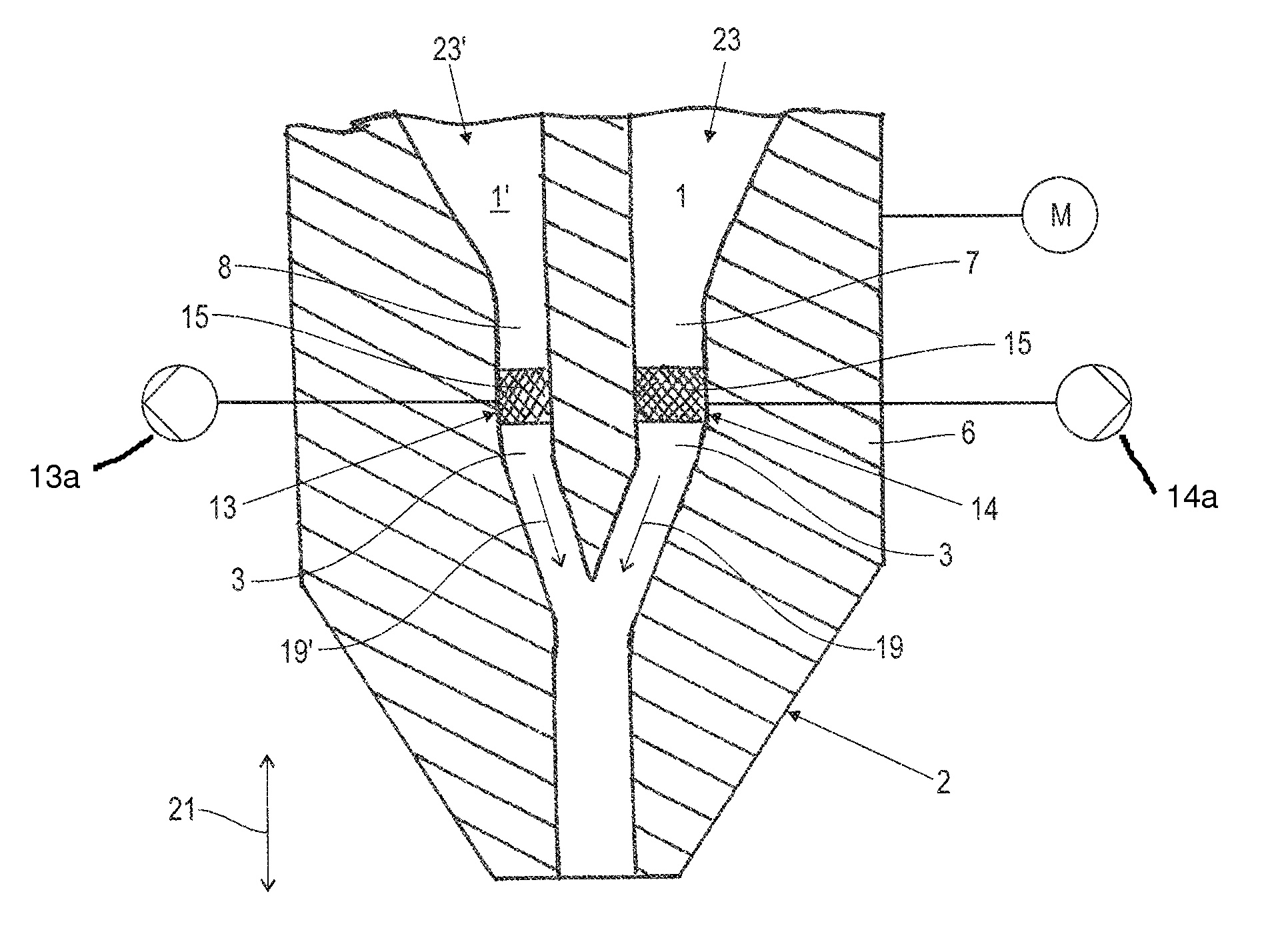
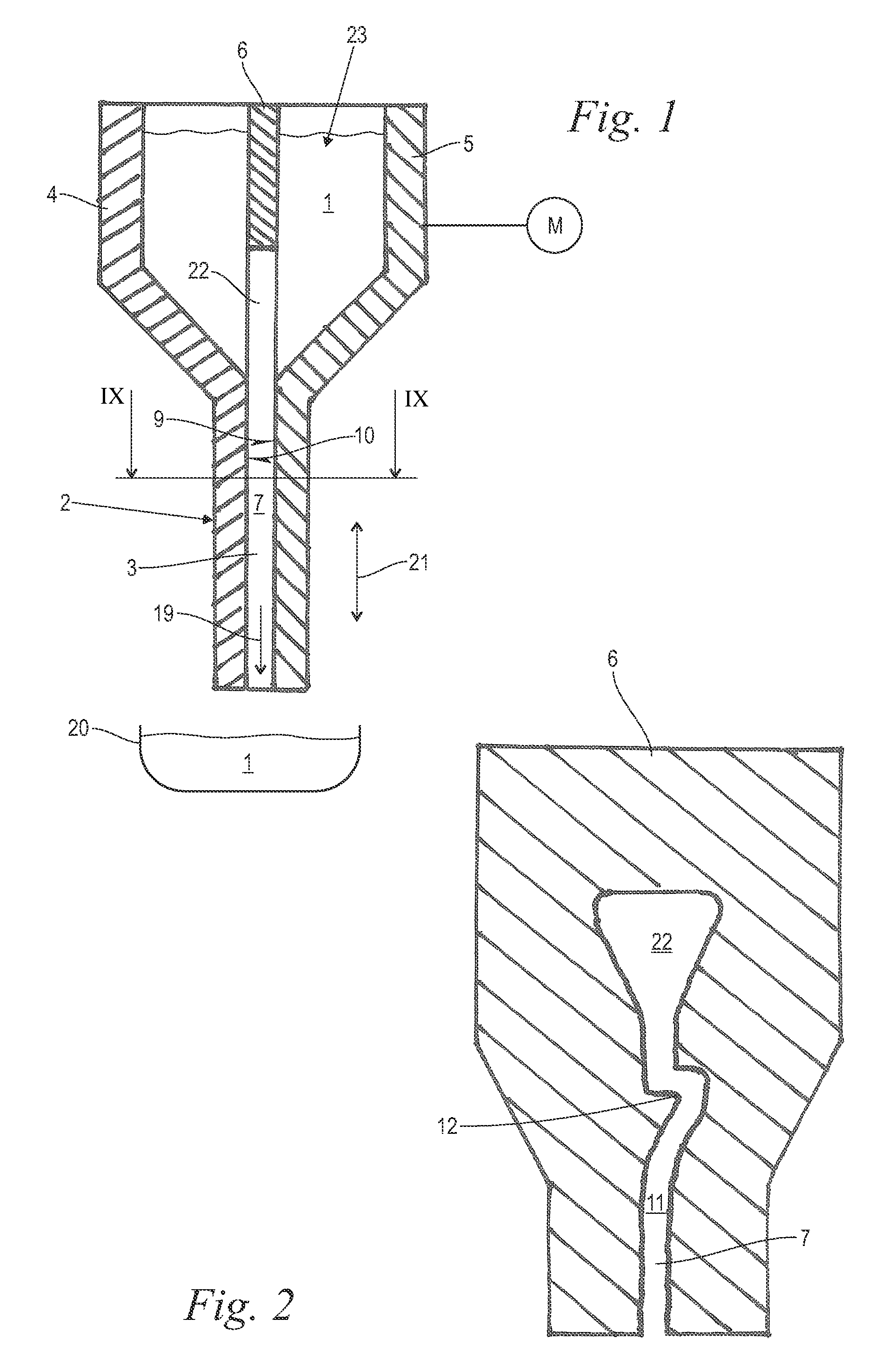
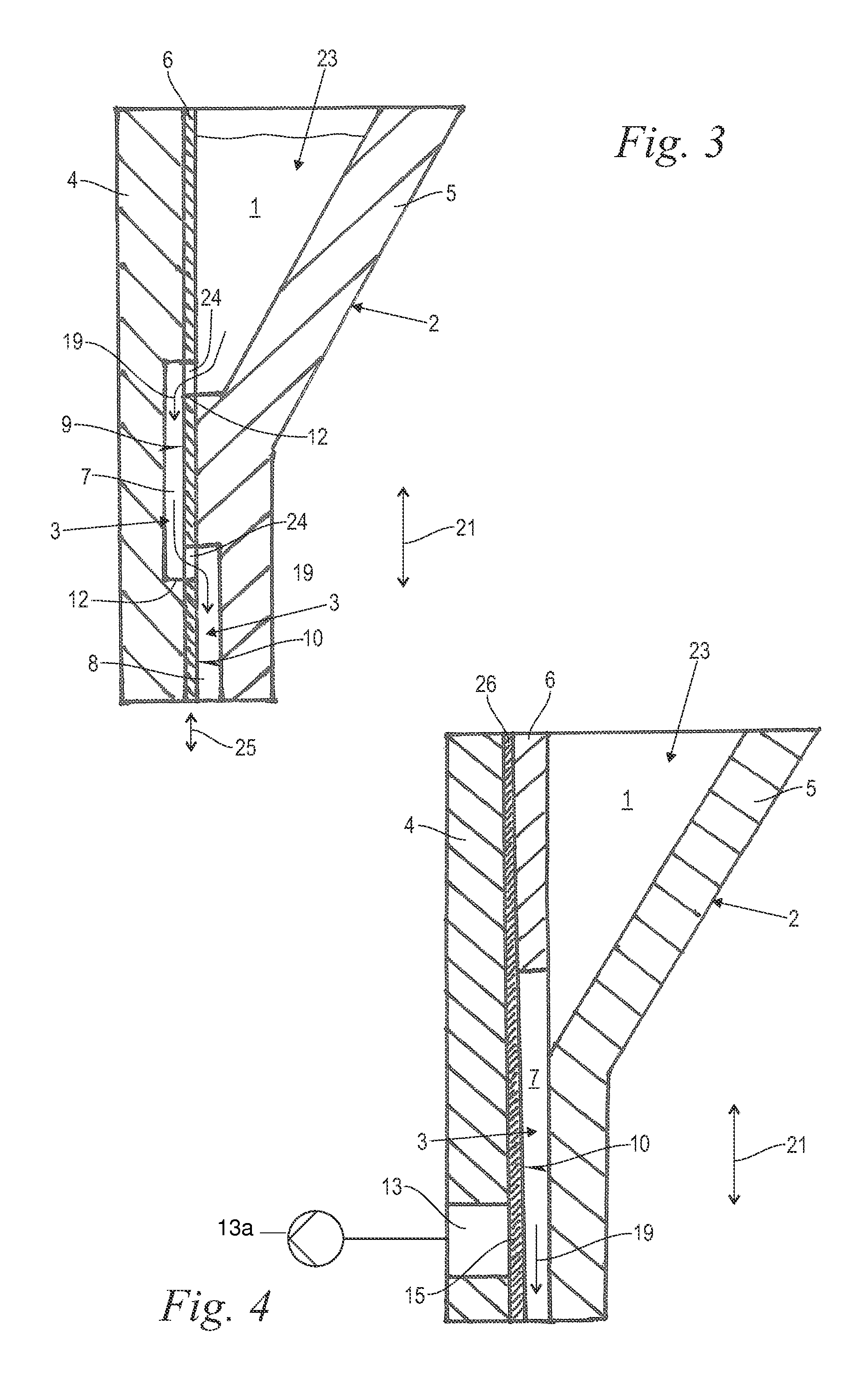
[0027]FIG. 1 shows in a cross-sectional illustration a first embodiment of the capillary metering device according to the invention. The capillary metering device comprises a vibration body 2 which is schematically illustrated and in which a capillary 3 is formed that is also schematically illustrated. The capillary 3 is vertical in operation, i.e., oriented parallel to the direction of the weight force. Above the capillary 3 a supply funnel 23 is provided in the vibration body 2 in which a powder product 1, in particular in the form of a medicament or food supplement in powder form, is stored and supplied to the capillary 3. Below the capillary metering device a target container 20, schematically indicated, is arranged into which a certain metered quantity of the powder product 1 is to be introduced by means of the capillary metering device.

[0028]The capillary 3 serves for receiving and conveying the powder product 1 into the target container 20. For this purpose, it is matched wit...


PUM


Abstract

A capillary metering device for a powder product has a vibration body with a capillary formed within the vibration body for receiving and conveying the powder product. The vibration body is formed of at least two adjoining body parts, wherein the capillary is formed as a channel with at least one open side in the demounted state in at least one of the body parts. The open side of the channel in the mounted state is closed off by the adjoining body part. The vibration body is caused to vibrate with such an amplitude and frequency that a powder flow of the powder product passes through the capillary formed in the vibration body into a target container and that upon reaching a target quantity of the powder product in the target container the powder flow to the target container is interrupted.

Description

BACKGROUND OF THE INVENTION[0001]The invention concerns a capillary metering device for a powder product comprising a vibration body with a capillary formed within the vibration body for receiving and conveying a powder product; the invention also concerns a method for metering a powder product by means of such a capillary metering device.[0002]Fine-grain powder products, in particular medicaments in powder form, food supplements and the like, must be precisely metered in order to achieve a certain precisely measured administration dosage. Such precisely metered dosage quantities are, for example, filled into hard gelatin capsules or are pressed to tablets.[0003]Frequently, for metering the powder product so-called capillary metering devices are employed. They comprise a vibration body with a capillary that is formed in the vibration body for receiving and conveying the powder product. The cross-section of the substantially vertically oriented capillary is sized and adapted to the m...

Claims


Application Information

Patent Timeline
Patent Type & Authority Patents(United States)
IPC IPC(8): B67D7/74A61J3/07B65D83/06B65B1/08G01F11/28G01F13/00B65B1/36B65B1/30
CPCA61J3/07B65B1/08B65B1/30B65B1/36G01F13/001G01F13/006B65D83/06G01F11/282
Inventor WEIGEL, MARCO
Owner HARRO HOFLIGER VERPACKUNGSMASCHEN
Learn More