Rocker latch for controlling engine valve actuation

a technology of engine valves and latches, applied in the direction of machines/engines, output power, combustion air/fuel air treatment, etc., can solve the problems of internal combustion engines that may shudder and shake, and it is difficult to achieve adequate high cranking speed

Active Publication Date: 2016-08-09
JACOBS VEHICLE SYST
View PDF11 Cites 3 Cited by
  • Summary
  • Abstract
  • Description
  • Claims
  • Application Information

AI Technical Summary

Benefits of technology

[0008]Responsive to the foregoing challenges, Applicant has developed an innovative system for preventing a rocker arm actuated engine valve from closing, said system comprising: a rocker arm pivotally mounted on a rocker shaft; a structure mounted adjacent to the rocker arm in a fixed position relative to the rocker arm; a latch piston slidably disposed between the rocker arm and the structure, and a latch piston actuator operatively connected to the latch piston, wherein said latch piston is adapted to assume an extended position causing the latch piston to engage both the rocker arm and the structure to limit the pivotal motion of the rocker arm, wherein the latch piston actuator is adapted to exert a force on the latch piston to cause the latch piston to assume the extended position or to retract from the extended position, and wherein the latch piston further comprises an engagement surface adapted to maintain the latch piston in the extended position continuously when the latch piston actuator ceases to exert force on the latch piston.

Problems solved by technology

During start-up and shut-down, an internal combustion engine may shudder and shake as it compresses air at low engine speeds.
Moreover, it may be particularly difficult to achieve adequately high cranking speeds, to charge and activate the valve actuation system with hydraulic fluid when the fluid is cold and has a higher viscosity.

Method used


Image

  • Rocker latch for controlling engine valve actuation
  • Rocker latch for controlling engine valve actuation
  • Rocker latch for controlling engine valve actuation

Examples


Embodiment Construction

[0027]Reference will now be made in detail to embodiments of the systems and methods of the present invention, examples of which are illustrated in the accompanying drawings. As embodied herein, embodiments of the present invention include systems and methods of actuating one or more engine valves.

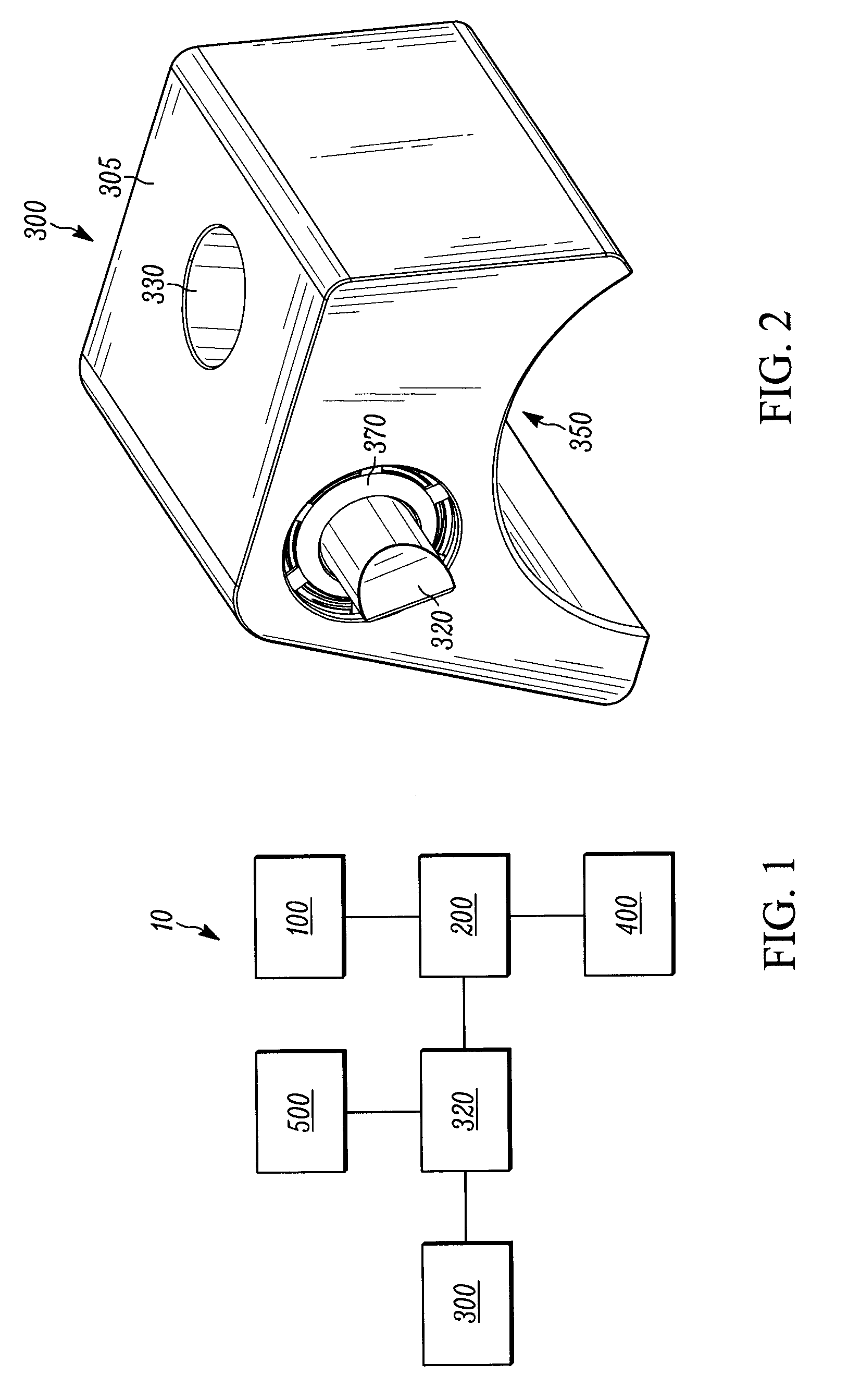
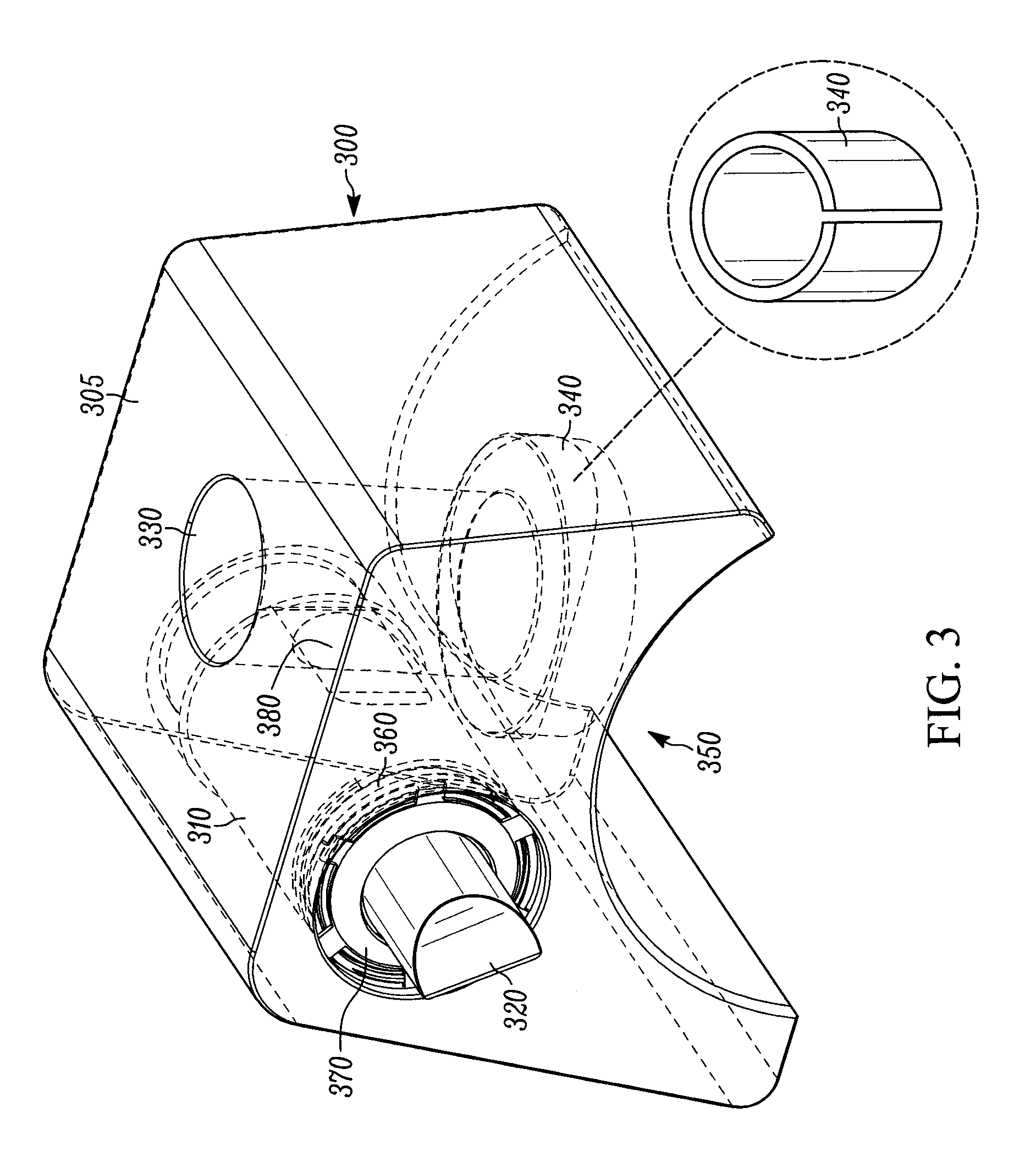
[0028]An embodiment of the present invention is shown schematically in FIG. 1 as valve actuation system 10. The valve actuation system 10 may include a rocker actuator 100, such as a cam, push tube, or other valve train element, operatively connected to a rocker arm 200. The rocker actuator 100 may be adapted to selectively apply motion to the rocker arm 200. The rocker arm 200 may be operatively connected to one or more engine valves 400 or a valve bridge (not shown), which in turn may act on the engine valves. A structure 300, which is fixed in position relative to the pivoting rocker arm 200, may be mounted adjacent (i.e., near) to the rocker arm. A latch piston or bar 320 (collectively...


PUM


Abstract

Engine valve actuation systems and methods used to decompress an engine cylinder during engine start-up, shut-down, and for bleeder braking are disclosed. An exemplary system may include a rocker arm pivotally mounted on a rocker shaft, and a structure mounted adjacent to the rocker arm in a fixed position relative to the rocker arm. A latch piston may be slidably disposed between the rocker arm and the structure. The latch piston may be selectively extended to engage both the rocker arm and structure to limit the pivotal motion of the rocker arm and maintain the engine valves in an open condition.

Description

CROSS REFERENCE TO RELATED APPLICATIONS[0001]This application relates to, and claims the benefit of the earlier filing date and priority of U.S. Provisional Patent Application No. 61 / 738,794, filed on Dec. 18, 2012, and entitled “Rocker Latch For Controlling Engine Valve Actuation.”FIELD OF THE INVENTION[0002]The present invention relates generally to systems and methods for controlling engine valves in an internal combustion engine. In particular, the present invention relates to systems and methods for preventing an engine valve from closing when acted on by a pivoting rocker arm.BACKGROUND OF THE INVENTION[0003]Valve actuation in an internal combustion engine is required in order for the engine to produce positive power, as well as for engine braking. During positive power, intake valves may be opened to admit fuel and air into a cylinder for combustion. The exhaust valves may be opened to allow combustion gas to escape from the cylinder.[0004]Internal combustion engines may not ...

Claims


Application Information

Patent Timeline
Patent Type & Authority Patents(United States)
IPC IPC(8): F01L13/08F01L13/06F01L1/18F01L13/00
CPCF01L13/08F02M31/042F01L1/181F01L13/06F01L2760/001F02D2013/0292F01L2001/186F01L2013/0094F01L2800/01F01L2800/03F01L2810/03F01L2820/031F01L2820/034Y02T10/12F01L13/0015F02D13/0246
Inventor GRON, JR., G. MICHAELBALTRUCKI, JUSTIN DAMIENFUCHS, NEILLESTER, JOHN J.
Owner JACOBS VEHICLE SYST
Why Eureka
Try Eureka