
Tilting coupling device for timepiece

a coupling device and timepiece technology, applied in the field of timepiece coupling devices, can solve the problems of inconvenient use in extra-flat movements, space occupation, and paralyzed rotation of the corrector wheel, and achieve the effects of reducing bulk, reasonable production cost, and simple and robust structur

Active Publication Date: 2016-08-09
DE LA MFG DHORLOGERIE AUDEMARS PIGUET & CIE
View PDF33 Cites 2 Cited by
  • Summary
  • Abstract
  • Description
  • Claims
  • Application Information

AI Technical Summary

Benefits of technology

The present invention is aimed at providing a coupling device for timepieces that is compact, can be integrated into extra-flat movements, and has a simple and safe operation. The device limits the problem of parasitic rotation and can be used in various horological applications such as time-setting devices and chronograph watches. It has a fixed part of the frame of the timepiece and uses a tilting mechanism for coupling, which eliminates the parasitic rotation of the exit wheel. Overall, the device is easy to use, economical to manufacture, and reliable in operation.

Problems solved by technology

The coupling by translation, however, has the disadvantage that it may induce, in some circumstances, a parasitic rotation of the corrector wheel associated with the displacement of the mounted setting wheel along the circumference of this corrector wheel.
This may produce, for example, a slight jump, forwards or backwards, of the minutes hand when the user of the timepiece pushes the control stem after having set the time, which is clearly an inconvenience.
In addition, this type of coupling takes up a fair amount of space and therefore is not suitable for use in extra-flat movements.
This, however, brings problems due to the fact that, as in the case described above of setting the time, the translation of the mounted coupling and setting wheel can, in some circumstances, cause a parasitic rotation of the chronograph train and, consequently, a jump forward of the chronograph hand.
Although this does not influence the reading of the measured time because the gear play is made up subsequently, it is an aesthetical problem at the moment of actuation of the chronograph that should be eliminated.
There are also other applications that require a coupling in a timepiece that are affected by similar problems.
This layout, however, requires a complicated toothing on the coupling device setting wheel and increases the production cost.
At the same time, the space occupied by this mechanism remains considerable, and the mechanism requires a specific arrangement of the parts thereof relative to one another, which limits the use thereof both for functions other than a chronograph and in extra-flat movements.
Although this device can, in principle, be used for several applications such as the fast adjustment of the hours hand independently of the minutes hand or for the correction of the date, the mechanism is even more bulky than a conventional coupling and does not lend itself to integration in a flat movement.
In addition, the use of a fixed truncated conical axis of rotation in combination with a control of the inclination of the coupling pinion mounted on this axis by a number of springs does not appear to ensure reliable operation.
The mechanism is thus unsuitable for integration in extra-flat movements.
In addition, this coupling, respectively the corresponding correction device, can only control two functions and therefore is not suitable for high-end timepieces having a number of functions.
Again, this device can only control two functions, and the operation of said device does not appear to be reliable, given that the inclined position of the coupling wheel, following the release of the coupling wheel, is not obtained by stress, but by the action of the force of gravity, which changes in accordance with the orientation of the corresponding timepiece.
In spite of this layout the devices according to these documents do not lend themselves, for the reasons mentioned above, to integration in an extra-flat movement and are often affected by other disadvantages as explained above.
The device clearly is not suitable for use in an extra-flat movement, and the control of said device does not appear to be very reliable.
This system must have pinions of very small diameter in order to function, but also is unsuitable for integration in an extra-flat movement.
These devices in addition can only control a single function, which can be engaged or disengaged.
It must therefore be stated that, in spite of the significant number of pre-existing devices, the solutions of the prior art currently known for providing such a coupling, whether of the type having a coupling pinion in the same plane of rotation as the entry and exit wheels or of the type having a double coupling pinion on account of the distant planes of rotation of the entry and exit wheels, are not entirely satisfactory, are not suitable for certain applications, and cannot be used for any type of movements, in particular are not suitable for extra-flat movements.

Method used


Image

  • Tilting coupling device for timepiece
  • Tilting coupling device for timepiece
  • Tilting coupling device for timepiece

Examples


second embodiment

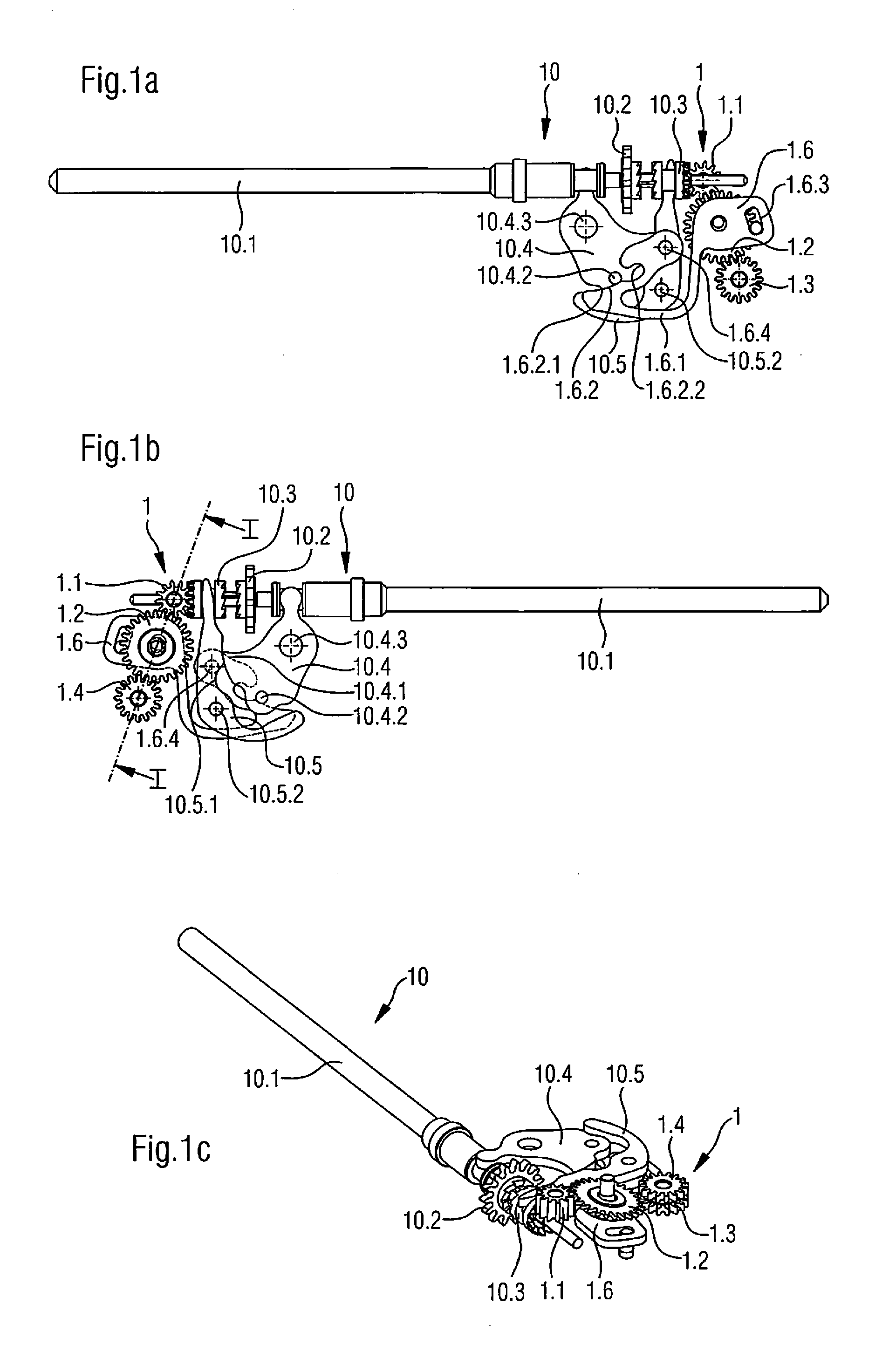
[0040]a coupling device according to the present invention, integrated in this case by way of example in a chronograph mechanism, is illustrated schematically in FIGS. 4a to 4d and 5a to 5d, which show a view from above, a view from the side, a perspective view and a longitudinal section of the chronograph mechanism in two different positions, i.e. when the chronograph is activated and when it is stopped. Although the other elements of this second embodiment of the coupling device, apart from a different form or placement without this resulting in a substantial difference, are identical compared with the device according to the first embodiment, the coupling device 1 in this application has only a single exit wheel 1.3. In addition, the movable element also provided in the form of a coupling yoke 1.6 here has a substantially different layout, which, however, does not change the function thereof.

[0041]In fact, the chronograph mechanism comprises a seconds wheel 1.1, which in this app...


PUM


Abstract

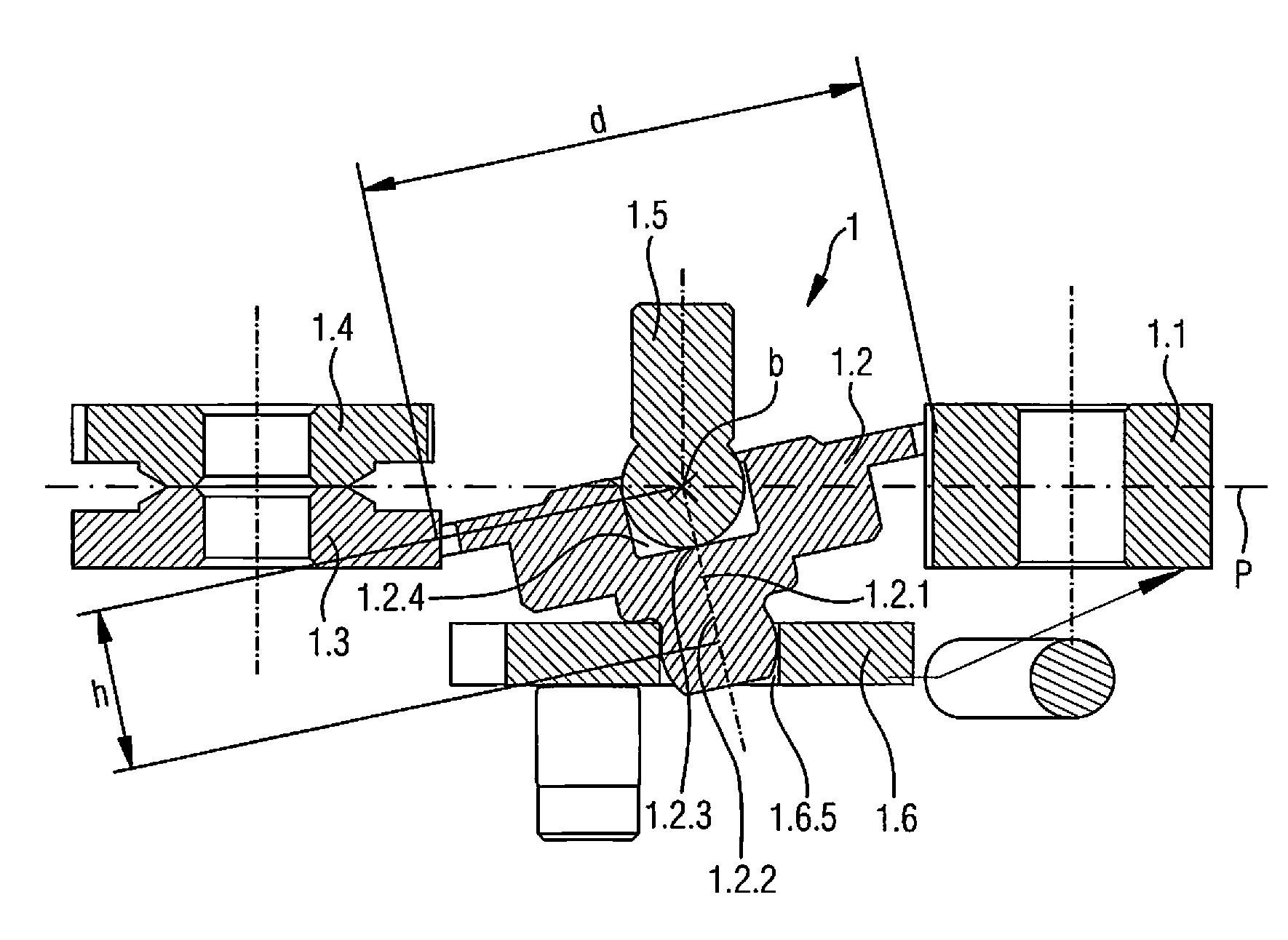
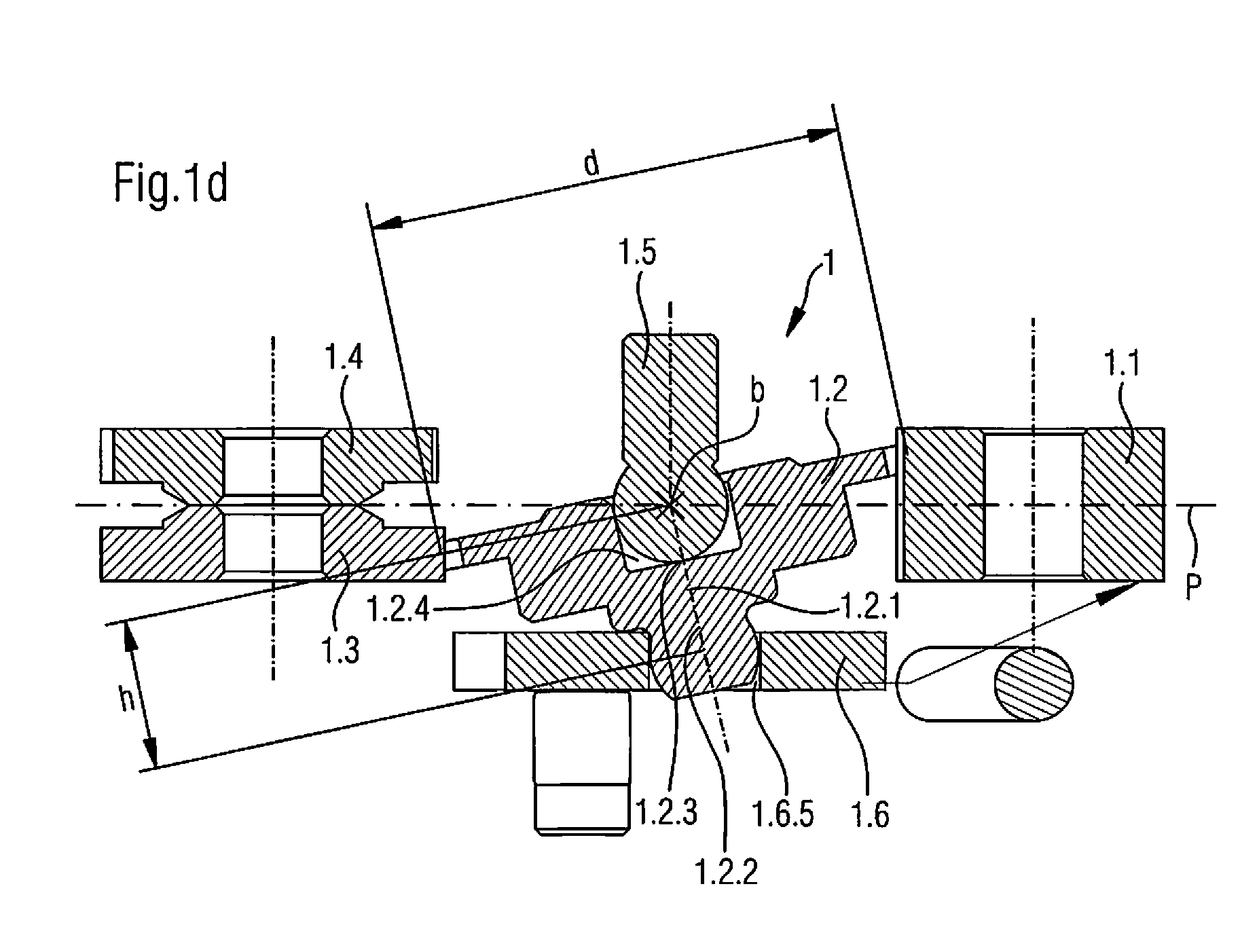
A coupling device for timepieces that includes an entry wheel, a coupling wheel, and a first exit wheel. The coupling wheel is disposed substantially coplanar to the plane of rotation of the entry wheel and of the first exit wheel and is adapted to tilt relative to the plane of rotation to occupy a first coupling position in which the coupling wheel meshes with the first exit wheel and a second coupling position in which the coupling wheel is decoupled from the first exit wheel. The device also includes a movable element to control the change of position between the first and the second position of the coupling wheel. The coupling wheel defines an axis of rotation that can be inclined relative to the normal to the plane of rotation of the entry wheel and of the first exit wheel by being mounted pivotably at each of the ends thereof.

Description

RELATED APPLICATION[0001]The present application claims priority to Swiss Patent Application No. 0933 / 14, filed Jun. 19, 2014, the disclosure of which is hereby incorporated by reference herein in its entirety.FIELD OF THE INVENTION[0002]The present invention relates to a coupling device for timepieces, in particular for time-setting devices or for chronograph watches, including timepieces having a mechanical movement, such as mechanical wristwatches.BACKGROUND OF THE INVENTION[0003]Timepieces having a mechanical movement, including mechanical wristwatches, are often equipped with a number of functions, in particular where fine watchmaking pieces are concerned, and thus normally has a control device having three positions, corresponding for example to the winding of the watch, the fast correction of the date, and the setting of the time, thus requiring a coupling in order to attribute the different functions to the corresponding positions of the control device. The conventional coup...

Claims


Application Information

Patent Timeline
Patent Type & Authority Patents(United States)
IPC IPC(8): G04F7/00G04B27/02G04B27/06G04F7/08G04B27/04
CPCG04B27/02G04F7/0828G04B27/06G04F7/0823G04F7/0838G04B27/04G04F7/08G04B27/023G04B27/045
Inventor PAGES, MARC-OLIVIERPAPI, GIULIOMUSITELLI, LAURENMONTET, JOHAN
Owner DE LA MFG DHORLOGERIE AUDEMARS PIGUET & CIE
Learn More