
Drainage structure for corrugated-fin heat exchanger

a heat exchanger and drain structure technology, applied in the field of drain structure of corrugated-fin heat exchangers, can solve the problems of reducing the area of heat transfer on the air side, reducing heat exchange performance, etc., and achieve the effects of enhancing drainage, reliably draining, and increasing draining ra

Active Publication Date: 2016-08-23
NIPPON LIGHT METAL CO LTD
View PDF6 Cites 1 Cited by
  • Summary
  • Abstract
  • Description
  • Claims
  • Application Information

AI Technical Summary

Benefits of technology

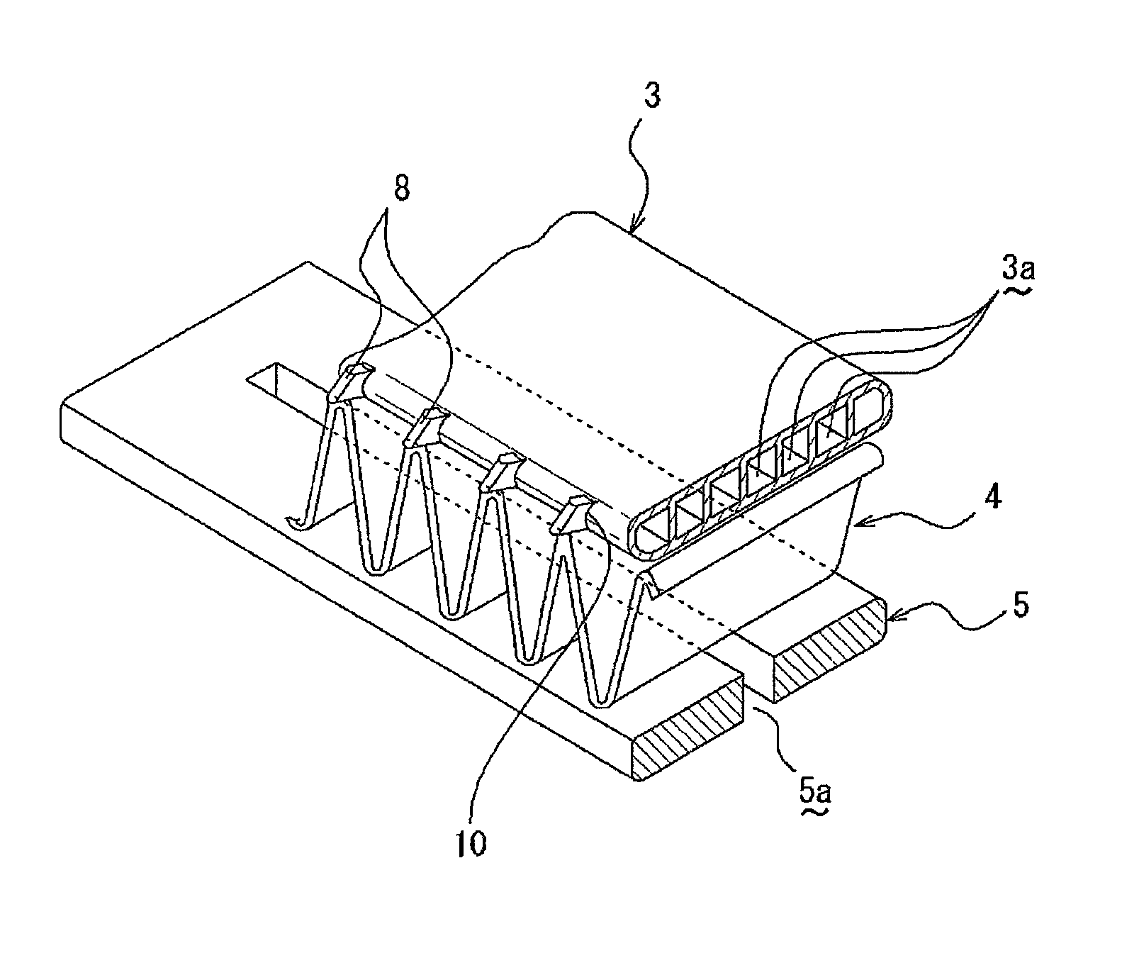
[0017]According to the present invention, under a state in which the water droplets adhering to the heat exchanger are retained between the corrugated fins, the end portions of the each of the lug pieces are brought into contact with the retained water, and therefore serve as the start point of the water fall. As a result, the water can be induced and drained reliably to the lower corrugated fin. Thus, even in a case where the flat heat exchange tubes are arranged in the horizontal direction, the drain rate can be increased and the drainage can be enhanced.

Problems solved by technology

As a result, there arises a problem of decrease in heat exchange performance.
When the fin pitch is increased, however, there is such a trade-off problem that the area of heat transfer on the air side is reduced.

Method used


Image

  • Drainage structure for corrugated-fin heat exchanger
  • Drainage structure for corrugated-fin heat exchanger
  • Drainage structure for corrugated-fin heat exchanger

Examples


Embodiment Construction

[0024]Now, referring to the accompanying drawings, detailed description is given of embodiments of the present invention.

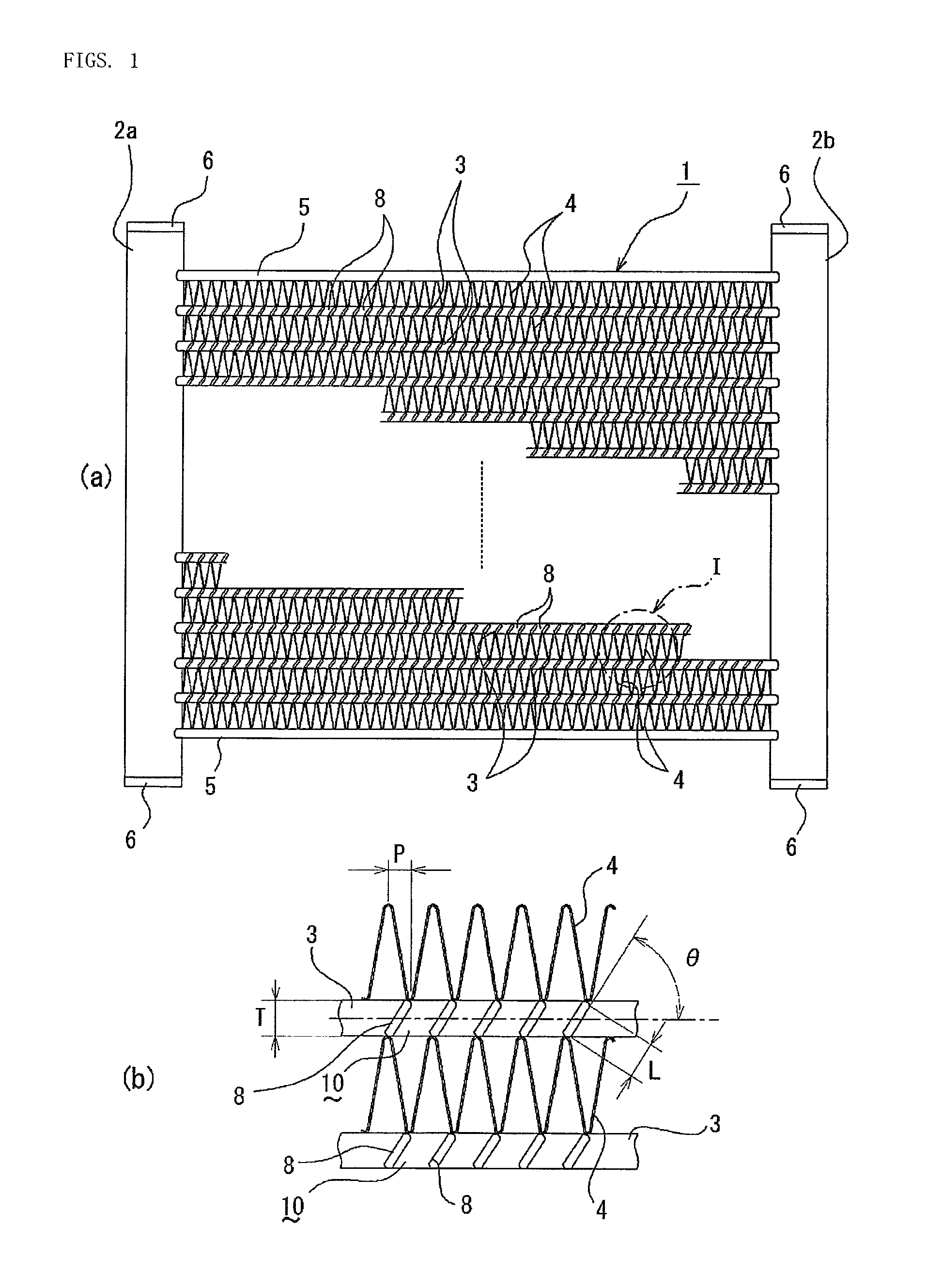
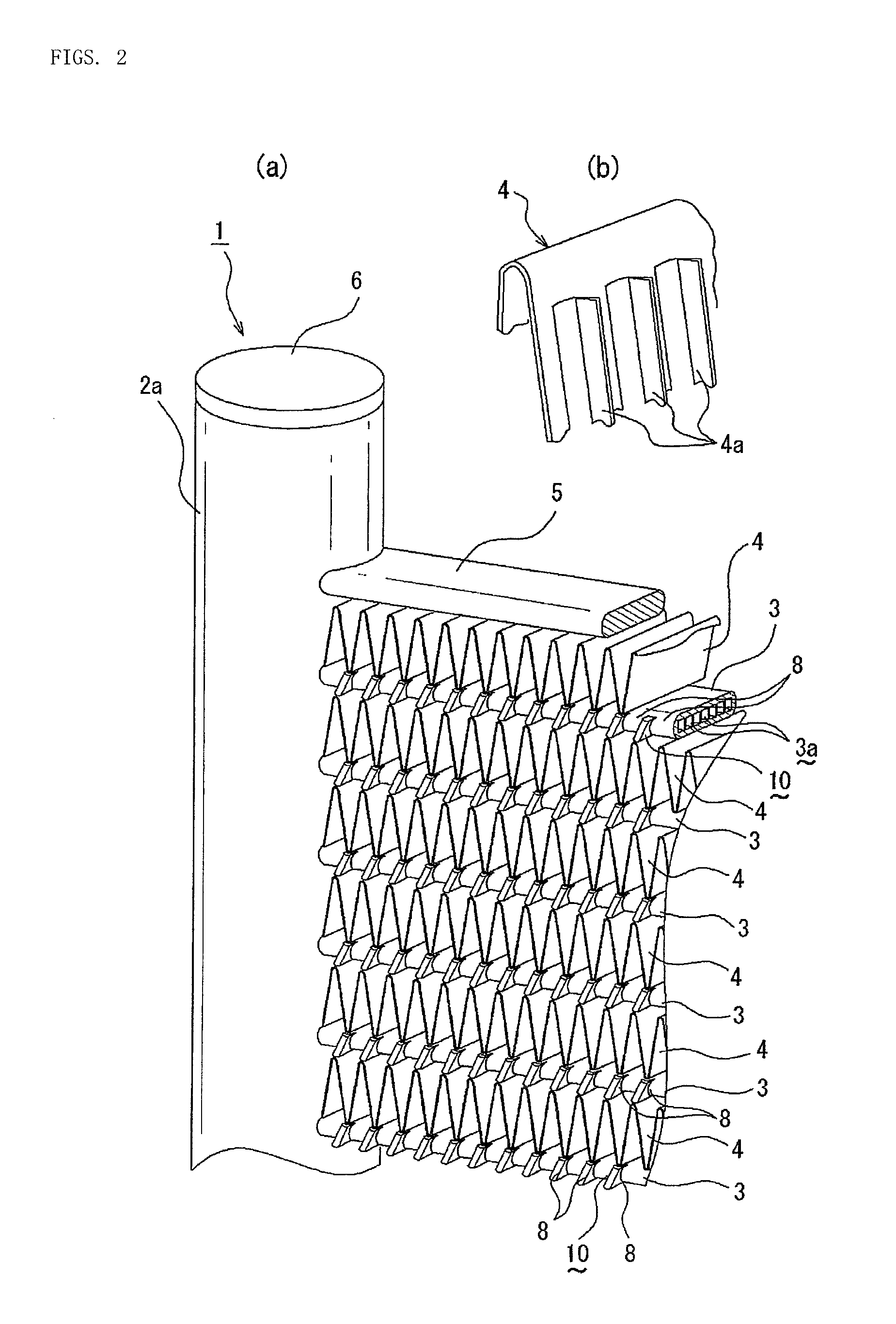
[0025]As illustrated in FIG. 1, a corrugated-fin heat exchanger 1 according to the present invention includes a pair of laterally opposing header pipes 2a and 2b each made of aluminum (including aluminum alloy), a plurality of flat heat exchange tubes 3 bridged (continuously provided) in parallel to one another in a horizontal direction between the header pipes 2a and 2b, and corrugated fins 4 each interposed between adjacent heat exchange tubes 3, the heat exchange tubes 3 and the corrugated fins 4 being brazed to the header pipes 2a and 2b.

[0026]In this case, the heat exchange tube 3 has a plurality of sectioned heating medium passages 3a formed therein. Further, on the upper outside and the lower opening side of the corrugated fins 4 at the upper and lower ends, side plates 5 made of aluminum are brazed, respectively. Further, at the upper and lower opening en...


PUM


Abstract

A corrugated-fin heat exchanger is constructed by arranging a plurality of flat heat exchange tubes parallel to each other in a horizontal direction between a pair of opposing header pipes, joining, at a position between the plurality of flat heat exchange tubes, corrugated fins formed by alternately repeating peak folding and valley folding portions, and forming water flow passages from lug pieces that are obtained by obliquely cutting and raising flange portions extending along end portions of each of the plurality of flat heat exchange tubes (3) in a width direction thereof. A pitch (P) of each of the corrugated fins between a peak and a valley thereof, a width (L) of each of the lug pieces in a vertical direction thereof, and a thickness (T) of the each of the plurality of flat heat exchange tubes have a relationship of P×2≧L≧T.

Description

TECHNICAL FIELD[0001]The present invention relates to a drain structure for a corrugated-fin heat exchanger, and more specifically, to a drain structure that is enhanced in drainage of a parallel flow heat exchanger having corrugated fins and flat heat exchange tubes alternately arranged therein.BACKGROUND ART[0002]In general, a corrugated-fin heat exchanger is widely used, which is constructed by arranging a plurality of flat heat exchange tubes parallel to one another in a horizontal direction between a pair of opposing header pipes, and joining corrugated fins between the heat exchange tubes. In a case where this type of corrugated-fin heat exchanger is used as an evaporator, condensed water (dew water) adheres to the surface thereof, which increases an airflow resistance, and further, inhibits heat transfer due to a resistance of a water film adhering to the surfaces of the corrugated fins. As a result, there arises a problem of decrease in heat exchange performance.[0003]Furthe...

Claims


Application Information

Patent Timeline
Patent Type & Authority Patents(United States)
IPC IPC(8): F25D21/14F28D1/053F28F17/00F28F1/12F25B39/02F28F1/26
CPCF28F17/005F28D1/05383F28F1/128F25D21/14F25B39/022F25B2500/01F28F1/26
Inventor YOSHIDA, TAKESHIYAMAZAKI, KAZUHIKO
Owner NIPPON LIGHT METAL CO LTD
Learn More