Structure of electrical connector

a technology of electrical connectors and connectors, applied in the direction of coupling devices, two-part coupling devices, electrical apparatus, etc., to achieve the effect of improving the structure of electrical connectors, improving structural strength, and convenient disassembly

Inactive Publication Date: 2016-08-23
KINNEXA
View PDF16 Cites 14 Cited by
  • Summary
  • Abstract
  • Description
  • Claims
  • Application Information

AI Technical Summary

Benefits of technology

[0005]In view of the above drawbacks, through collection of data and assessment and consideration in multiple aspects, in combination with years' experience in the associated business, the present inventor creates, through repeated trivial and modification, an improved structure of an electrical connector that improves structural strength for prevention of damage and improves an effect of coupling and fixation for prevention of detachment, while allowing for easy disengagement.
[0006]A primary object of the present invention is to prevent damage caused by a pulling force in insertion and removal.
[0007]Another primary object of the present invention is to prevent accidental detachment between mated male and female parts.
[0008]A further primary object of the present invention is to allow for easy disengagement of the male and female parts.
[0009]To achieve the above object, the present invention comprises at least one hook-up pin mounted on at least one lateral side of an electrical connector. The hook-up pin comprises at least one pin body. A plurality of soldering sections is formed on two sides of an end of the pin body for clamping and being soldered to a circuit substrate. At least one elastic pressing section is formed on an end of the pin body that is adjacent to the soldering sections. At least one hook section is formed on an end of the elastic pressing section that is distant from the soldering sections. When male and female parts of the present invention are inserted into each other, fixation can be achieved with the hook section so as to prevent unexpected detachment caused by factors including accidental impact. To disengage the male and female parts, it only needs to press down the elastic pressing section and easy disengagement can be achieved. Further, since the soldering sections are respectively set on two sides of the circuit substrate, the structural strength is enhanced to resist the force of insertion and removal. With the above-described technique, the problem that the conventional Super MHL suffers easy and unexpected detachment can be overcome and advantages that the structural strength is enhanced to prevent damage and an effect of coupling and fixing is enhanced, while easy disengagement is allowed, can be achieved.

Problems solved by technology

Thus, it is a challenge of the present inventor and those involved in this business to develop a solution that overcomes the above problems and deficiencies.

Method used


Image

  • Structure of electrical connector
  • Structure of electrical connector
  • Structure of electrical connector

Examples


Embodiment Construction

[0021]The following descriptions are exemplary embodiments only, and are not intended to limit the scope, applicability or configuration of the invention in any way. Rather, the following description provides a convenient illustration for implementing exemplary embodiments of the invention. Various changes to the described embodiments may be made in the function and arrangement of the elements described without departing from the scope of the invention as set forth in the appended claims.

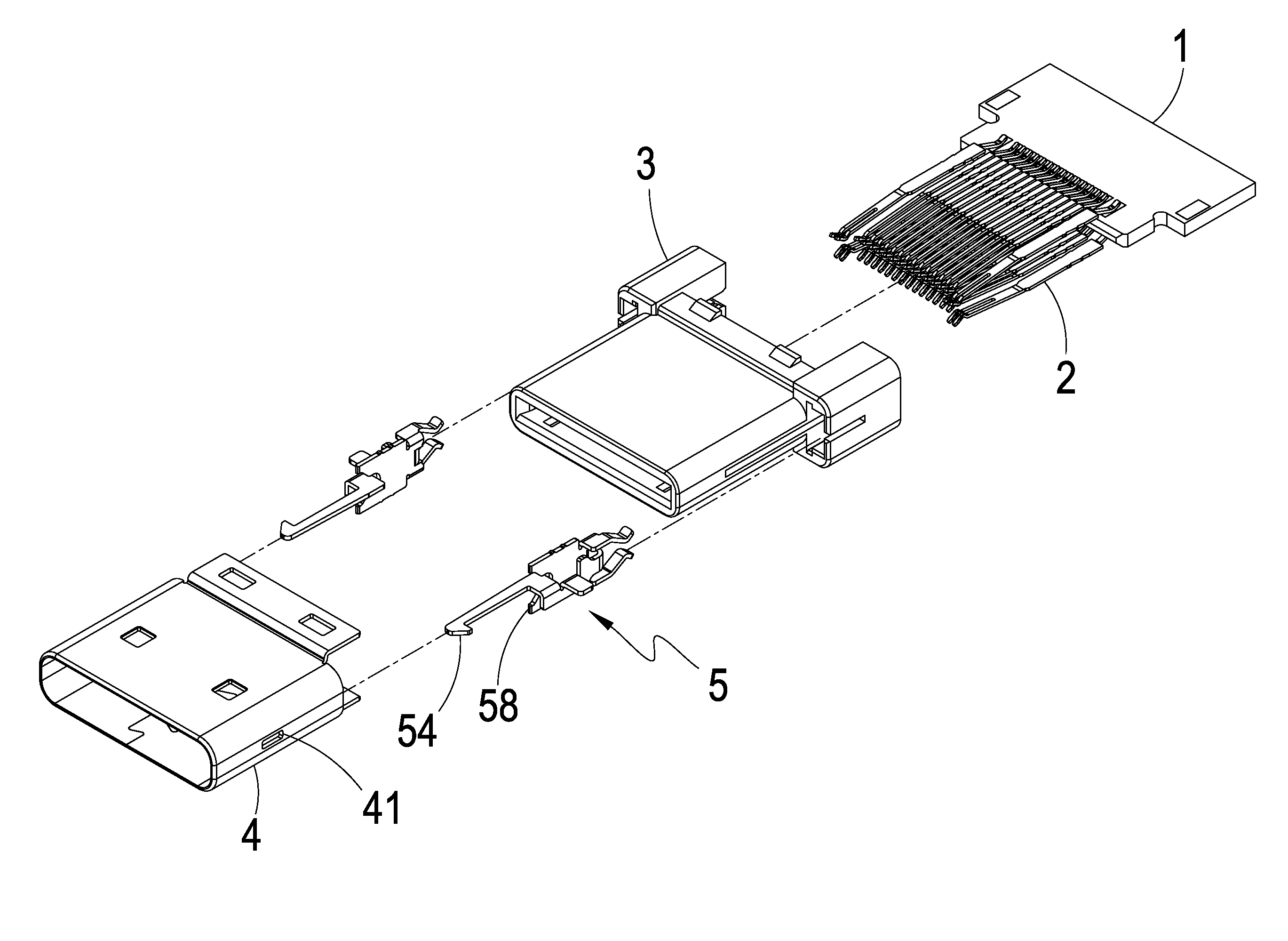
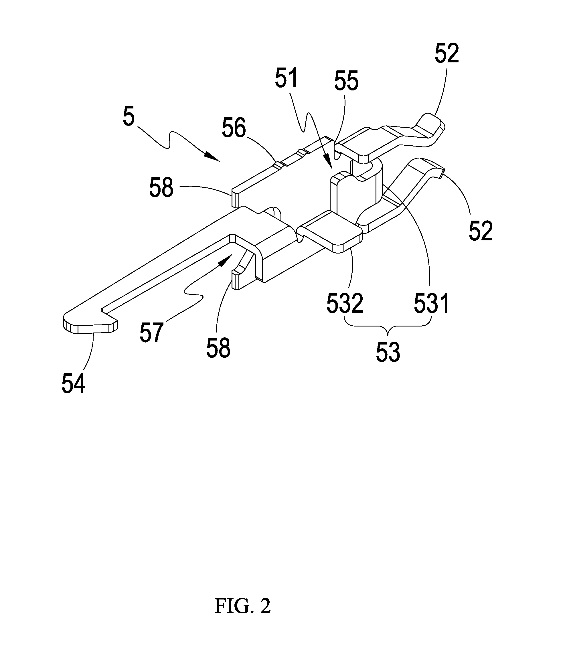
[0022]Referring to FIGS. 2-6, which are respectively a perspective view showing a hook-up pin of a preferred embodiment of the present invention, a schematic view showing, in a developed form, the hookup pin, a schematic view illustrating formation of the hook-up pin, a perspective view showing the preferred embodiment of the present invention, and a partial exploded view of the preferred embodiment of the present invention, these drawings clearly show that the present invention comprises at least o...


PUM


Abstract

An electrical connector includes a hook-up pin mounted on one lateral side of the electrical connector. The hook-up pin includes a pin body, soldering sections respectively formed on two sides of an end of the pin body, an elastic pressing section formed on an end of the pin body that is adjacent to the soldering sections, and a hook section formed on an end of the elastic pressing section that is distant from the soldering sections. The soldering sections are arranged to clamp and be soldered to opposite sides of the circuit substrate. In inserting male and female parts of the present invention to each other, the soldering sections clamp on and are soldered to two sides of the circuit substrate so as to be resistant to the force of insertion and removal and be protected against damage. Further, the hook section helps prevent undesired detachment.

Description

TECHNICAL FIELD OF THE INVENTION[0001]The present invention relates generally to an improved structure of an electrical connector, and more particularly to an improved structure of an electrical connector that improves structural strength for prevention of damage and improves an effect of coupling and fixation for prevention of detachment, while allowing for easy disengagement.DESCRIPTION OF THE PRIOR ART[0002]The process of time and science and technology bring various sorts of electronic devices that are full of the market. These electronic devices have been long closely involved in our lives. For electrical connection to be established among various electronic devices and for suiting all sorts of needs of use of the electronic devices, a number of different types of connectors are now available. And, all sorts of connectors are under development and researches for new specifications for the purposes of enhancing the performances thereof. For example, high definition multimedia in...

Claims


Application Information

Patent Timeline
Patent Type & Authority Patents(United States)
IPC IPC(8): H01R24/60H01R13/66H01R107/00
CPCH01R24/60H01R13/665H01R2107/00H01R12/707H01R12/724H01R13/6275H01R13/6658
Inventor CHIEN, SHIN-HAOQUINLAN, JOHN PATRICK
Owner KINNEXA
Why Eureka
Try Eureka