Circuit calibrating method and circuit calibrating system

a circuit and calibrating method technology, applied in the field of circuit calibrating methods and circuit calibrating systems, can solve the problems of large signal drift, sudden rise of errors, undesired values of all characteristics, etc., and achieve the effect of reducing signal drift, increasing the tolerance range for signal drift, and effectively reducing signal drift for analog control signals

Active Publication Date: 2016-08-23
PIXART IMAGING INC
View PDF9 Cites 0 Cited by
  • Summary
  • Abstract
  • Description
  • Claims
  • Application Information

AI Technical Summary

Benefits of technology

[0011]Accordingly, one objective of the present application is to provide a circuit calibrating method that can reduce signal drift and increase a tolerance range.
[0012]Another objective of the present application is to provide a circuit calibrating system that can reduce signal drift and increase a tolerance range.
[0015]In view of above-mentioned embodiments, the signal drift for the analog control signal can be effectively reduced, to avoid that the signal drift is over a tolerance range. Please note, besides the advantage of decreasing the signal drift, the present invention can further provide an advantage of “increasing the tolerance range for the signal drift.

Problems solved by technology

Some drift may occur during the manufacturing process for a circuit, such that all characteristics (ex. current, voltage, capacitance, and resistance) may have undesired values.
However, such control method may cause larger signal drift.
However, such error may suddenly raises up for a specific stage of digital control code.
However, such method needs a decoder, which always occupies a large region of the circuit, to convert the original digital control codes to control codes which can activate ACS generating units in sequence.

Method used


Image

  • Circuit calibrating method and circuit calibrating system
  • Circuit calibrating method and circuit calibrating system
  • Circuit calibrating method and circuit calibrating system

Examples


Embodiment Construction

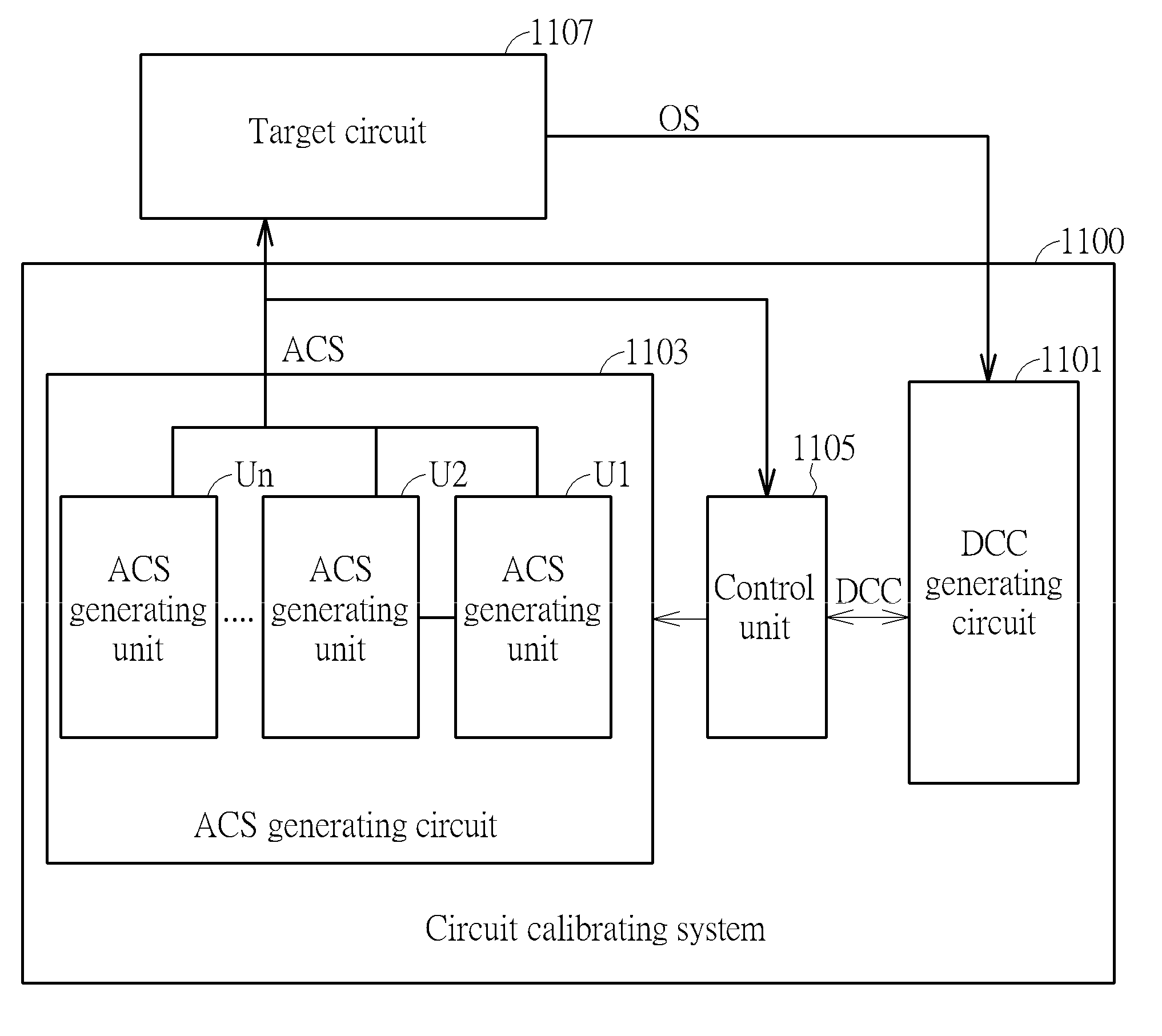
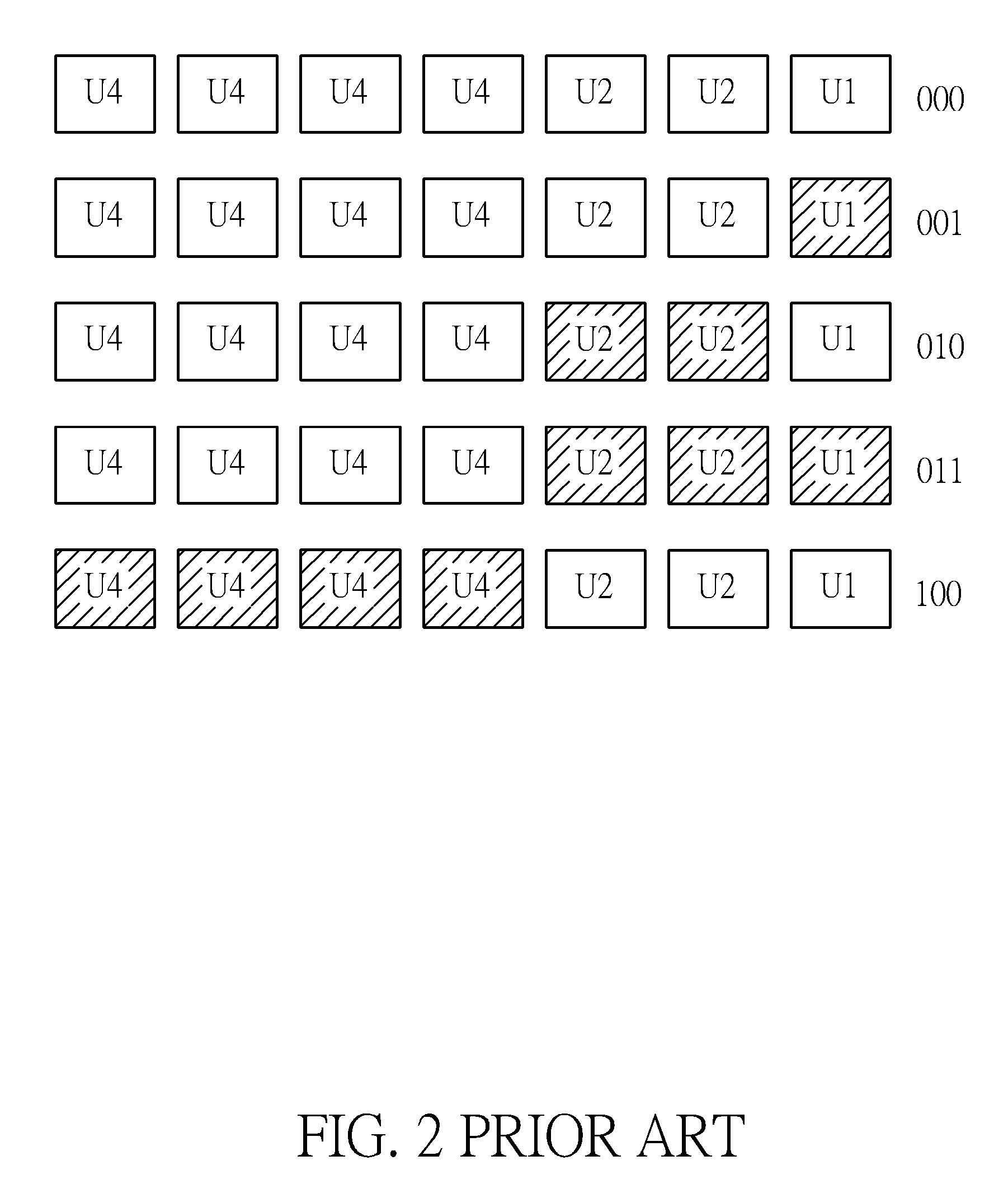
[0026]Some embodiments are provided in following descriptions to solve the issue for prior art: A specific stage of digital control code or some stages of digital control codes make corresponding analog control signal(s) generates larger signal drift. FIG. 5 is a schematic diagram illustrating a difference between the ideal output and the actual output for the ACS generating circuit, in one embodiment of the present invention. Please note, the embodiment in FIG. 5 applies the example in FIG. 3 for explaining, but it does not mean the scope of the present invention is limited to FIG. 3. In FIG. 3, the fourth stage of digital control code makes the ACS generating circuit have a larger signal drift. Accordingly, in the embodiment of FIG. 5, ACS generating units activated by the fourth stage of digital control code are adjusted. That is, adjust the ideal output of the ACS generating circuit if the fourth stage of digital control code is applied. By this way, a difference between the ide...


PUM


Abstract

A circuit calibrating method, applied to an ACS generating circuit, which comprises a plurality of ACS generating units and activates the ACS generating unit corresponding to different DCCs to generate difference ACSs. The circuit calibrating method comprises: (a) determining which one of the ACSs has a large difference from an ideal value thereof; (b) adjusting a number of the ACS generating units, which are activated by a DCC corresponding to the ACS acquired in the step (a), or a next stage of the DCC corresponding to the ACS acquired in the step (a); and (c) generating the ACS to a target circuit, according to the number of the ACS generating circuits adjusted in the step (b).

Description

BACKGROUND OF THE INVENTION[0001]1. Field of the Invention[0002]The present invention relates to a circuit calibrating method and a circuit calibrating system, and particularly relates to a circuit calibrating method and a circuit calibrating system which can control the number of active analog control signal generating units to reduce signal drift.[0003]2. Description of the Prior Art[0004]Some drift may occur during the manufacturing process for a circuit, such that all characteristics (ex. current, voltage, capacitance, and resistance) may have undesired values. Accordingly, a calibrating mechanism is needed.[0005]FIG. 1 is a block diagram illustrating the prior art circuit calibrating system. As shown in FIG. 1, the circuit calibrating system 100 comprises a digital control code generating circuit 101 (hereinafter, a DCC generating circuit)and an analog control signal generating circuit 103 (hereinafter, an ACS generating circuit). The DCC generating circuit 101 is applied to ge...

Claims


Application Information

Patent Timeline
Patent Type & Authority Patents(United States)
IPC IPC(8): H03M1/10H03M1/12
CPCH03M1/1028H03M1/12H03M1/10H03M1/66
Inventor HWANG, HSIANG-WEICHEN, YUNG-HUNGLIU, HAN-CHI
Owner PIXART IMAGING INC
Why Eureka
Try Eureka