Circuit correction method and circuit correction system

A correction method and correction system technology, applied in logic circuits, electrical components, pulse technology, etc., can solve the problem of large circuit area of ​​the decoder, and achieve the effect of reducing signal drift and avoiding signal drift.

Active Publication Date: 2016-07-20
PIXART IMAGING INC
View PDF4 Cites 0 Cited by
  • Summary
  • Abstract
  • Description
  • Claims
  • Application Information

AI Technical Summary

Problems solved by technology

Therefore, the different ACS generation units in the ACS generation units activated by the number handle 011 and 100 can be reduced to one, but this type of approach requires a decoder to change the original number handle into a controllable ACS generation unit with the required sequence start handle
The decoder often requires a larger circuit area in the circuit

Method used


Image

  • Circuit correction method and circuit correction system
  • Circuit correction method and circuit correction system
  • Circuit correction method and circuit correction system

Examples


Embodiment Construction

[0037] It should be understood that the specific embodiments described here are only used to explain the present invention, not to limit the present invention.

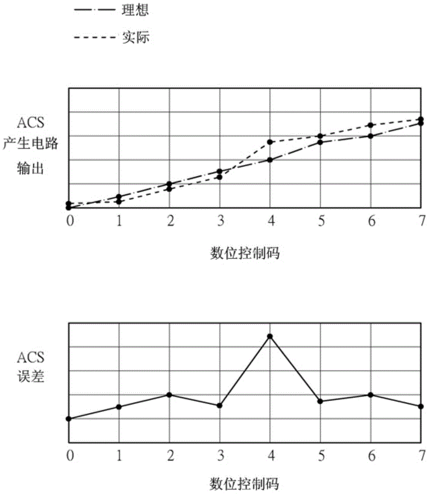
[0038] The following will describe how to improve the problem that a certain level or certain levels of digital handles will cause a large signal drift of the corresponding analog control signal. Figure 5 A schematic diagram illustrating the difference between the ideal output and the actual output of the ACS generating circuit in an embodiment of the present invention is shown. Figure 5 The embodiment of the aforementioned image 3 The example is used as an example, but it is not limited that the present invention can only be used in image 3 situation. exist image 3 Among them, the digital handle of the 4th order will make the ACS generation circuit have a large signal drift, so in Figure 5 In the embodiment, the ACS generating unit activated by the 4th-order digital handle is adjusted, that is, when the 4th...


PUM


Abstract

The invention discloses a circuit correction method. The circuit correction method is used on an analog control signal generation circuit, the analog control signal generation circuit comprises a plurality of analog control signal generation units and will correspondingly start analog control signal generation units to generate different analog control signals according to different digital handles. The circuit correction method comprises the following steps: (a) calculating which analog control signal among the analog control signals has an actual value different from an ideal value; (b) regulating the number of the analog control signal generation units started by the digital handle corresponding to the analog control signal calculated in the step (a) or the digital handle of an adjacent order; and (c) generating the analog control signal for a target circuit according to the number of the ACS generation units regulated in the step (b). The invention further discloses a corresponding circuit correction system. By adopting the circuit correction method disclosed by the invention, the signal drift of the analog control signal can be effectively reduced and the signal drift is prevented from exceeding an admissible range.

Description

technical field [0001] The present invention relates to a circuit calibration method and a circuit calibration system, in particular to a circuit calibration method and a circuit calibration system for reducing signal drift by changing the number of activated analog control signal generating units. Background technique [0002] During the manufacturing process of the circuit, process drift will occur, so that various characteristics of the circuit (such as current, voltage, capacitance, resistance) will be different from expectations. Therefore, a correction mechanism is needed to correct the integrated circuit. [0003] figure 1 A block diagram of a circuit calibration system in the prior art is shown. Such as figure 1 As shown, the circuit calibration system 100 includes a digital handle generation circuit 101 (hereinafter referred to as a DCC generation circuit for short) and an analog control signal generation circuit 103 (hereinafter referred to as an ACS generation ...

Claims


Application Information

Patent Timeline
Patent Type & Authority Applications(China)
IPC IPC(8): H03K19/00
Inventor 黄翔伟陈永宏刘汉麒
Owner PIXART IMAGING INC
Why Eureka
Try Eureka