Variable displacement swash plate compressor

a compressor and variable displacement technology, applied in the direction of machines/engines, pump control, positive displacement liquid engines, etc., can solve the problems of adversely affecting the operation of the actuator in such compressors and control, and achieve the effect of superior controllability

Inactive Publication Date: 2016-08-30
TOYOTA IND CORP
View PDF24 Cites 15 Cited by
  • Summary
  • Abstract
  • Description
  • Claims
  • Application Information

AI Technical Summary

Benefits of technology

[0010]It is an object of the present invention to provide a variable displacement swash plate compressor that has superior controllability when changing the compressor displacement.
[0011]To achieve the above object, one aspect of the present invention is a variable displacement swash plate compressor provided with a housing including a suction chamber, a discharge chamber, a swash plate chamber, and a cylinder bore. A drive shaft is supported to be rotatable in the housing. A swash plate is rotatable in the swash plate chamber when the drive shaft rotates. A link mechanism is arranged between the drive shaft and the swash plate. The link mechanism allows an inclination angle of the swash plate to be changed relative to a direction orthogonal to a rotation axis of the drive shaft. A piston is reciprocated in the cylinder bore. A conversion mechanism reciprocates the piston in the cylinder bore with a stroke corresponding to the inclination angle when the swash plate rotates. An actuator is capable of changing the inclination angle. A control mechanism controls the actuator. The actuator is arranged in the swash plate chamber to be rotatable integrally with the drive shaft. The actuator includes a movable body coupled to the swash plate, a fixed body fixed to the drive shaft, and a control pressure chamber defined by the movable body and the fixed body. The drive shaft is inserted into the movable body to allow movement of the movable body in an axial direction. The actuator is configured to move the movable body with an interior pressure of the control pressure chamber. The movable body includes a circumferential wall that extends in a direction along the rotational axis and surrounds the fixed body. The fixed body includes a guide portion that projects in the direction along the rotational axis and extends along an inner surface of the circumferential wall. The movable body contacts the guide portion to restrict inclination of the movable body relative to the drive shaft that is greater than or equal to a predetermined amount.
[0012]In the compressor of the present invention, the actuator includes the movable body, the fixed body, and the control pressure chamber, and the circumferential wall is formed in the movable body. The circumferential wall extends in the axial direction and surrounds the fixed body. The fixed body includes the guide portion that projects in the axial direction along the inner surface of the circumferential wall. Thus, in the compressor, even if the suction reaction force and the compression reaction force acting on the piston is transmitted to the actuator through the swash plate and the link mechanism, contact of the movable body with the guide portion moves the movable body in the axial direction while restricting inclination of the movable body relative to the drive shaft over a predetermined amount or greater. Thus, in the compressor, the actuator is easily operated in a suitable manner, and the controllability for varying the compressor displacement is improved.

Problems solved by technology

This adversely affects the operation of the actuator in such compressors and the control for varying the compressor displacement.

Method used


Image

  • Variable displacement swash plate compressor
  • Variable displacement swash plate compressor
  • Variable displacement swash plate compressor

Examples


Embodiment Construction

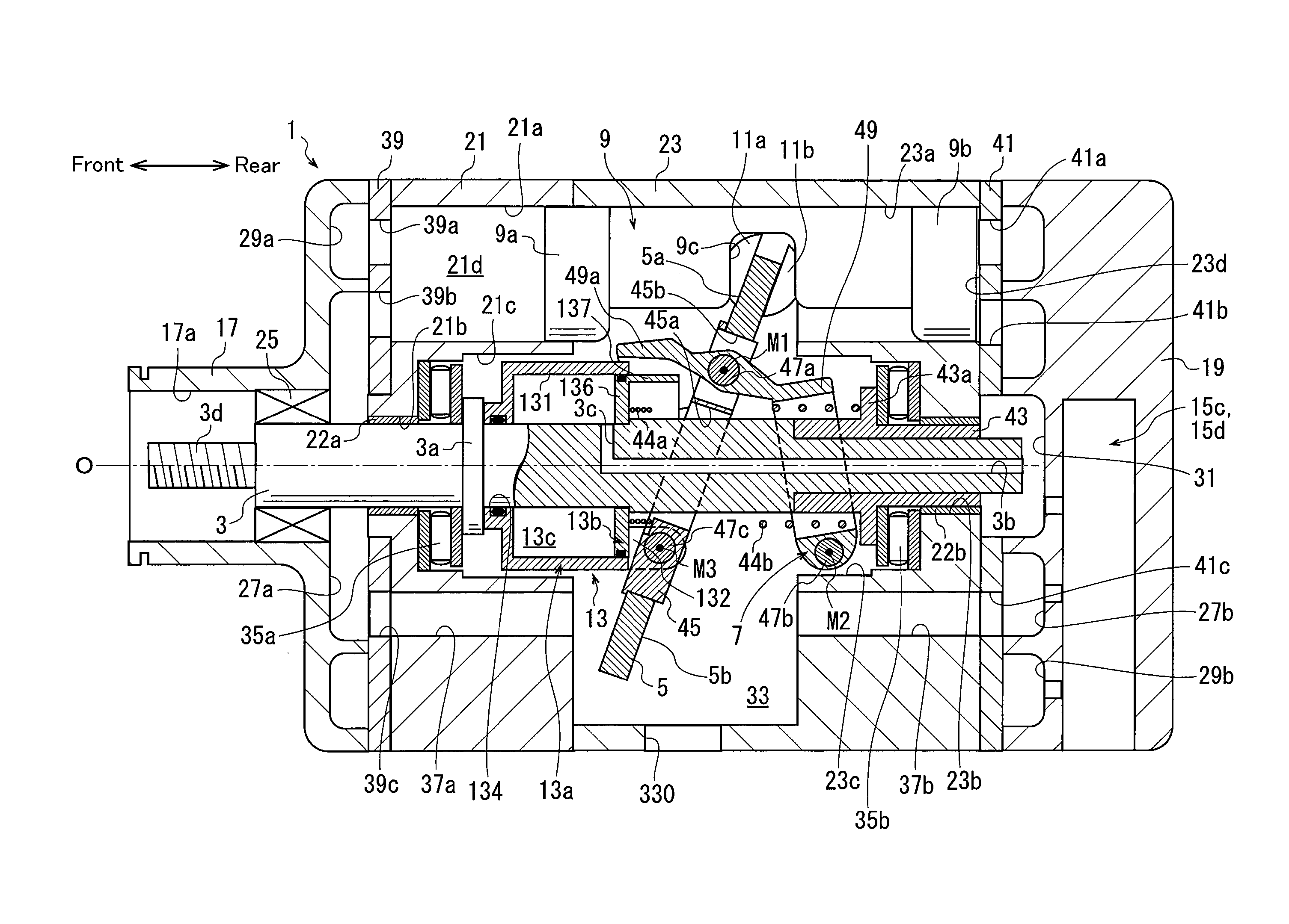
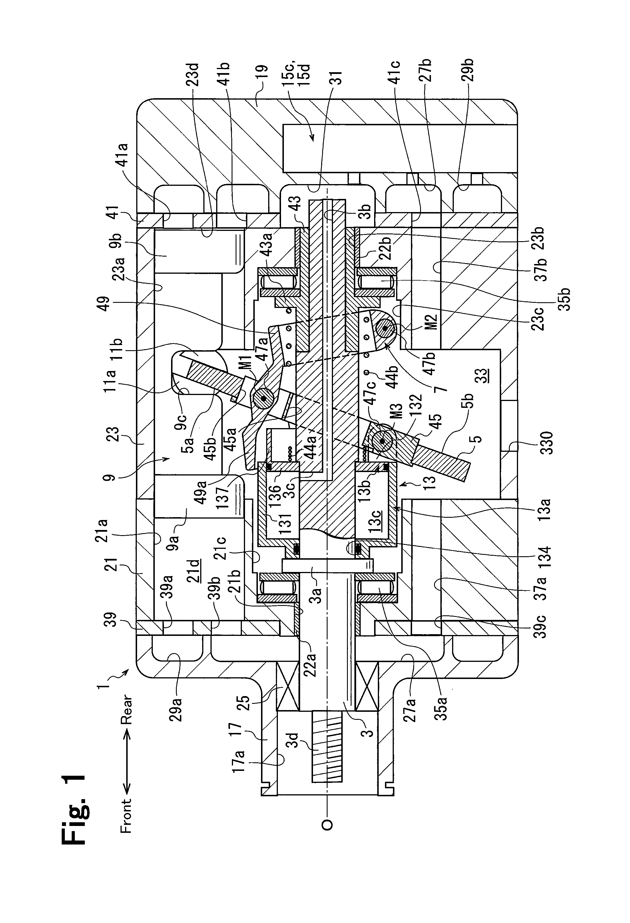
[0035]One embodiment of the present invention will now be described with reference to the drawings. A compressor of the present embodiment is a variable displacement double-headed swash plate compressor. The compressor is installed in a vehicle and forms a refrigeration circuit of a vehicle air conditioner.

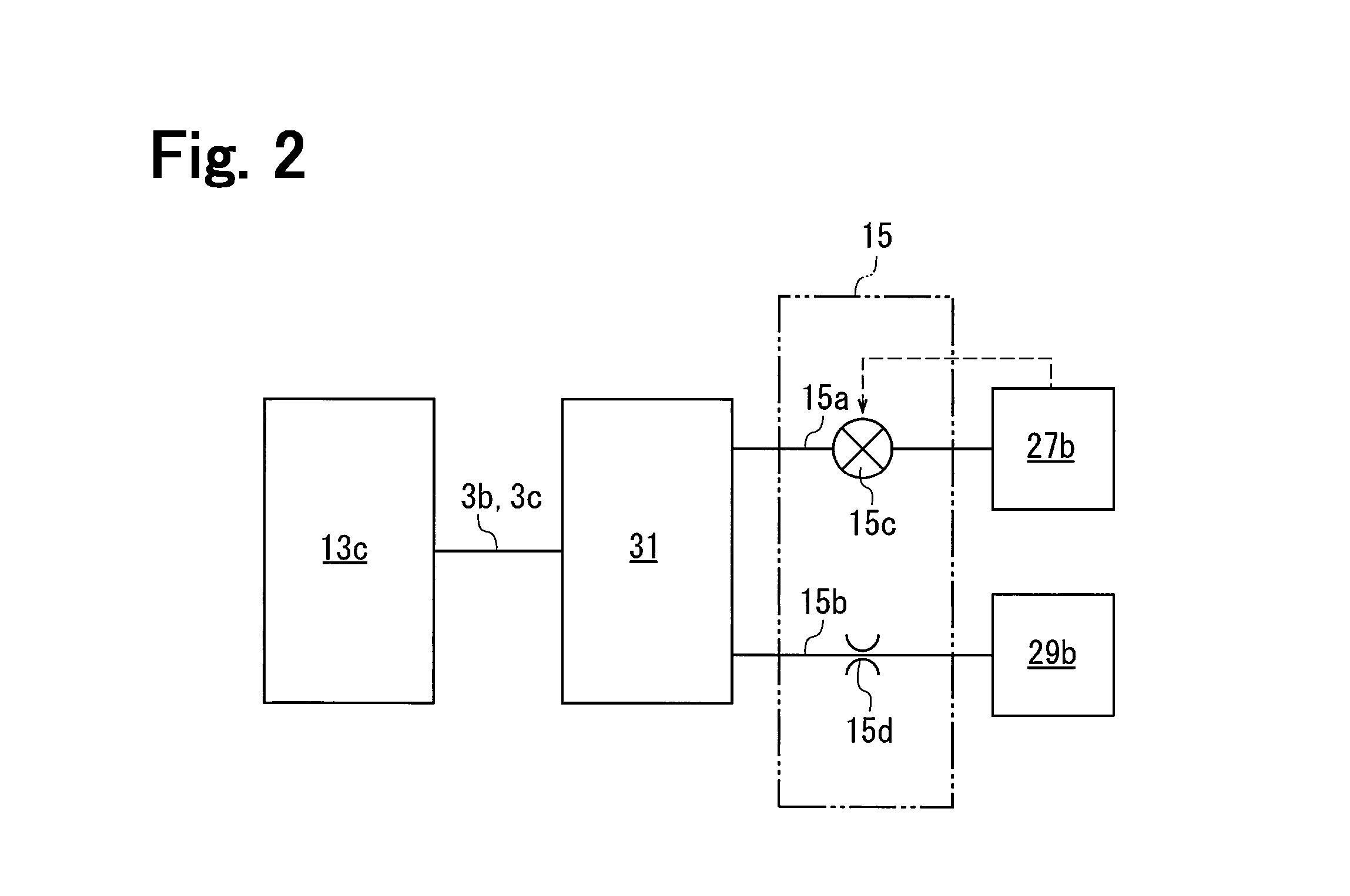
[0036]As shown in FIG. 1, the compressor includes a housing 1, a drive shaft 3, a swash plate 5, a link mechanism 7, a plurality of pistons 9, pairs of shoes 11a and 11b, an actuator 13, and a control mechanism 15, which is shown in FIG. 2. In FIG. 1, the shape of the actuator 13 and the like is simplified to facilitate illustration. The same applies to FIG. 3.

[0037]As shown in FIG. 1, the housing 1 includes a front housing segment 17, which is located at the front of the compressor, a rear housing segment 19, which is located at the rear of the compressor, and a first cylinder block 21 and a second cylinder block 23, which are located between the front housing segment 17 and the ...


PUM


Abstract

A variable displacement swash plate compressor is provided with a housing, a drive shaft, a swash plate, a link mechanism, a piston, a conversion mechanism, an actuator, and a control mechanism. The housing includes a suction chamber, a discharge chamber, a swash plate chamber, and a cylinder bore. The actuator includes a movable body coupled to the swash plate, a fixed body fixed to the drive shaft, and a control pressure chamber defined by the movable body and the fixed body. The movable body includes a circumferential wall extending in a direction along a rotational axis and surrounding the fixed body, which includes a guide portion projecting in an axial direction along an inner surface of the circumferential wall. The movable body contacts the guide portion to restrict inclination of the movable body relative to the drive shaft that is greater than or equal to a predetermined amount.

Description

BACKGROUND OF THE INVENTION[0001]The present invention relates to a variable displacement swash plate compressor.[0002]Japanese Laid-Open Patent Publication No. 5-172052 and Japanese Laid-Open Patent Publication No. 52-131204 each disclose a variable displacement swash plate compressor (hereinafter referred to as compressor). Each compressor is provided with a housing including a suction chamber, a discharge chamber, a swash plate chamber, and a plurality of cylinder bores. The housing rotatably supports a drive shaft. The swash plate chamber accommodates a swash plate, which is rotated when the drive shaft rotates. A link mechanism is arranged between the drive shaft and the swash plate to change an inclination angle of the swash plate. The inclination angle is an angle relative to a direction orthogonal to the rotation axis of the drive shaft. A piston accommodated in each cylinder bore reciprocates and forms a compression chamber in the cylinder bore. When the swash plate rotates...

Claims


Application Information

Patent Timeline
Patent Type & Authority Patents(United States)
IPC IPC(8): F04B27/10F04B27/16F04B27/18F04B1/29
CPCF04B1/295F04B27/1072F04B27/18F04B27/1804F04B2027/1813F04B27/08F04B27/0873F04B49/00
Inventor SUZUKI, TAKAHIROOTA, MASAKIYAMAMOTO, SHINYAHONDA, KAZUNARINISHII, KEIYAMAZAKI, YUSUKE
Owner TOYOTA IND CORP
Why Eureka
Try Eureka