Method for arranging transmissions on a downlink carrier

a transmission and downlink technology, applied in the direction of payload allocation, digital transmission, transmission path sub-channel allocation, etc., can solve the problems of increasing equipment cost and complexity, increasing the cost and complexity of equipment, and not being able to specify a large number of bandwidth configurations by a standard, so as to achieve the effect of better utilization of available spectrum resources

Active Publication Date: 2016-08-30
HUAWEI TECH CO LTD
View PDF6 Cites 3 Cited by
  • Summary
  • Abstract
  • Description
  • Claims
  • Application Information

AI Technical Summary

Benefits of technology

[0018]Thus, it is realized that to maximize the spectrum utilization and deployment flexibility of the system, it is desirable that radio carriers could have scalable bandwidth. Thereby, the carrier could fit into the available spectrum resource while minimizing any unused amount of frequency resources.
[0019]Therefore, the invention increases the bandwidth scalability within a current set of supported transmission bandwidth configurations.
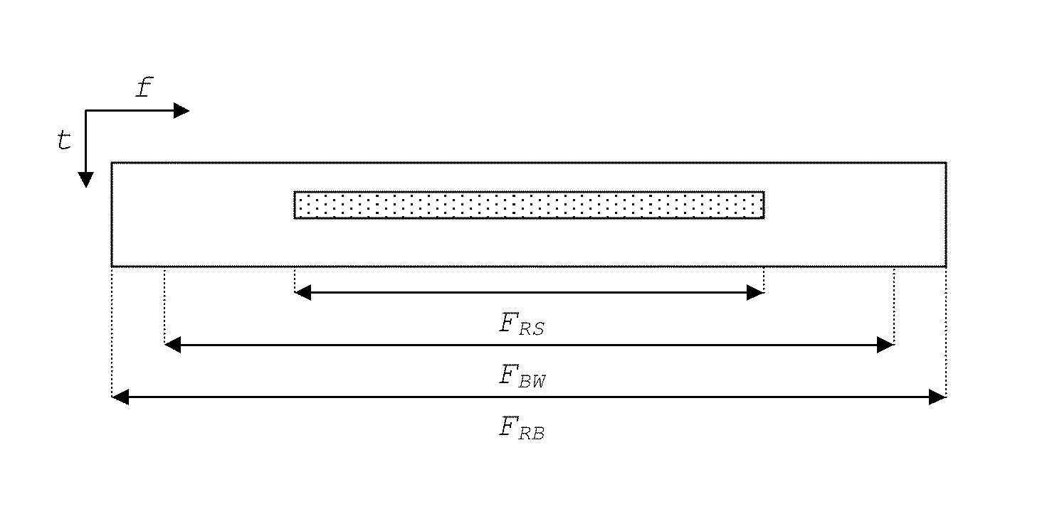
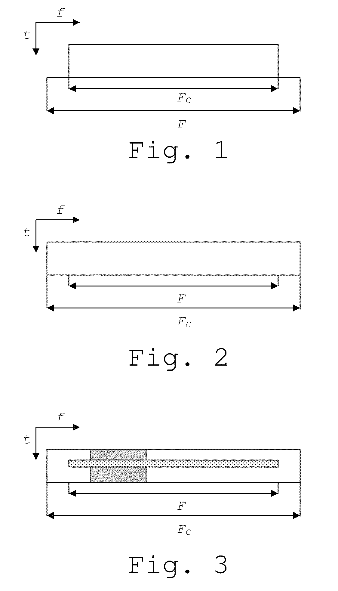
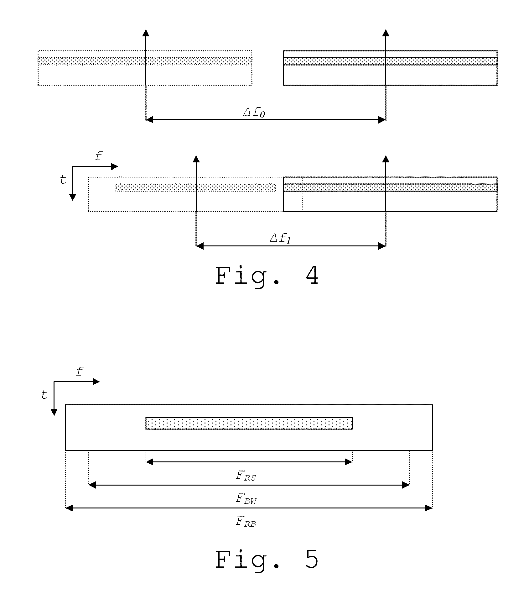
[0020]The method of the invention increases the bandwidth scalability of a carrier, where the bandwidth of said carrier belongs to a set of configured bandwidth configurations. The method allows for deploying a carrier with a bandwidth that is larger than the bandwidth available and using data scheduling to control the spectral containment of the signal. The invention discloses a method using a downlink carrier on which cell-specific reference signals can be configured with a bandwidth being smaller than the carrier bandwidth.

Problems solved by technology

Unfortunately, the carrier bandwidths that radio communications systems can provide have always limited flexibility.
However, for each bandwidth configuration it is needed to specify performance requirements for various channels, spectral masks for out-of-band emissions, test cases for transmitters and receivers, etc, which increases the cost and complexity of the equipment.
Thus making a large number of bandwidth configurations specified by a standard is not practical.
In a number of real-life LTE deployment cases it has been already noticed that these bandwidths do not perfectly match the spectrum allocations available to the operators.
The additional problem for the operators is that not all carrier bandwidths are supported by the LTE standard in all frequency bands, so carrier aggregation will not always be possible.
In the given example a 3 MHz LTE carrier might not be possible to deploy in the remaining spectrum because all the carrier bandwidths are not defined in all frequency bands.
Even if carrier aggregation is used as in the above example, there could still be left-over spectrum that is not used, so this obviously is not the most efficient solution.
However, set aside the issues with standardization and testing, it would also be a problem to determine suitable values for new bandwidth configurations that would fit most system deployments world wide.
Hence, introducing new transmission bandwidth configurations poses problems for system operators that already have deployed a system, as different carriers will be accessible to terminals of different system releases.
The sum of the channel bandwidths of the normal LTE carrier and the segments cannot be larger than 20 MHz, because one control channel (located on the normal LTE carrier) is used for scheduling transmission on both the normal LTE carrier and the segments, while the control channel of the normal LTE carrier cannot handle resource allocation for larger channel bandwidths.
It means that extension carrier cannot be operated stand-alone and must be part of carrier aggregation.
However, when the bandwidth of an available spectrum resource does not match a combination of supported bandwidths, there is still a waste of such spectrum resources that will be left unused.

Method used


Image

  • Method for arranging transmissions on a downlink carrier
  • Method for arranging transmissions on a downlink carrier
  • Method for arranging transmissions on a downlink carrier

Examples


Embodiment Construction

[0039]In the following the invention is discussed, often in the context of a Long Term Evolution (LTE) mobile communications system. It should be noted that any such reference to LTE should be considered as an example intended to elucidate the invention. The invention itself is applicable to any mobile radio communications system with the right prerequisites, as discussed below.

[0040]The prior art solutions of extension carrier and carrier segments open up for more flexible usage of the available spectrum. However, a major limitation would occur if these new carrier types also would be confined to a small set of bandwidths. In that case, the bandwidth granularity is not straightforwardly increased. According to the previous example, if 19 MHz is available, a 15 MHz extension carrier may need to be deployed, possibly combined with aggregation of a 3 MHz carrier. Hence, the efficient use of available bandwidth is still a problem of the prior art solutions.

[0041]Suppose a frequency ran...


PUM


Abstract

A method is provided for arranging transmissions on a downlink carrier c, spanning a frequency range Fc, in a mobile radio communications system, wherein a bandwidth of Fc belongs to a set of predefined channel bandwidths in the communications system, and wherein the carrier c comprises a reference signal defined in the communications system. A configurable frequency range FRS comprising a set of time-frequency resources for comprising the reference signal of the carrier c is provided. Information associated with the configuration of said frequency range FRS is signaled to a receiver in the communications system, such that c can be deployed over a frequency range F smaller than Fc when the frequency range FRS is configured within F and any other transmissions on the carrier c are arranged to be within F.

Description

CROSS-REFERENCE TO RELATED APPLICATIONS[0001]This application is a National Stage of International Application No. PCT / CN2011 / 072941, filed on Apr. 18, 2011, which is hereby incorporated by reference in its entirety.FIELD OF THE INVENTION[0002]The present invention concerns a method for arranging transmissions on a downlink carrier in a mobile radio communications system. Further, it concerns a radio base station and a mobile terminal.BACKGROUND ART[0003]A wireless cellular communication system typically comprises one or several radio carriers, on which information is transmitted. The bandwidth of a radio carrier would have to be chosen such that it can be accommodated within the spectrum resources the system operator has at its disposal. The spectrum allocated to a certain system operator is often a consequence of national regulatory decisions and may be technology neutral.[0004]Unfortunately, the carrier bandwidths that radio communications systems can provide have always limited ...

Claims


Application Information

Patent Timeline
Patent Type & Authority Patents(United States)
IPC IPC(8): H04W72/04H04L5/00
CPCH04L5/0044H04L5/0048H04W72/0453
Inventor POPOVIC, BRANISLAVBERGGREN, FREDRIK
Owner HUAWEI TECH CO LTD
Why Eureka
Try Eureka