
Method for fuel injection control

a fuel injection and control method technology, applied in the direction of electric control, machines/engines, output power, etc., can solve the problems of not being able to meet the mandated low pm emission standards, the effect of increasing power output, increasing fuel efficiency, and increasing power outpu

Active Publication Date: 2016-09-06
FORD GLOBAL TECH LLC
View PDF41 Cites 5 Cited by
  • Summary
  • Abstract
  • Description
  • Claims
  • Application Information

AI Technical Summary

Benefits of technology

The patent text describes a method for improving engine performance and reducing emissions by adjusting the amount of fuel delivered to each cylinder through both direct injection and port injection based on the temperature of the intake valves. By increasing the amount of fuel delivered through the port injector as the intake valve temperature increases, the amount of fuel evaporated and homogenized in the intake port is increased, reducing emissions and improving engine performance. Overall, this method allows for a customized fuel injection profile for each cylinder that improves fuel efficiency and power output while reducing emissions.

Problems solved by technology

However, direct injected engines usually have higher particulate matter emissions (or soot) due to diffuse flame propagation wherein fuel may not adequately mix with air prior to combustion.
However, the inventors herein have identified potential issues with such an approach.
However, there may be conditions at low engine speed-load operating regions where the intake valve temperature is not sufficiently warm.
If a higher proportion of port injection is scheduled for a cylinder where the intake valve is not sufficiently warm, particulate matter emissions may actually be increased.
As a result, even with the shift towards more port injection, particulate matter (PM) emissions may not be sufficiently reduced to meet the mandated low PM emission standards.
In addition, due to inefficient fuel vaporization, engine performance may be degraded.

Method used


Image

  • Method for fuel injection control
  • Method for fuel injection control
  • Method for fuel injection control

Examples


Embodiment Construction

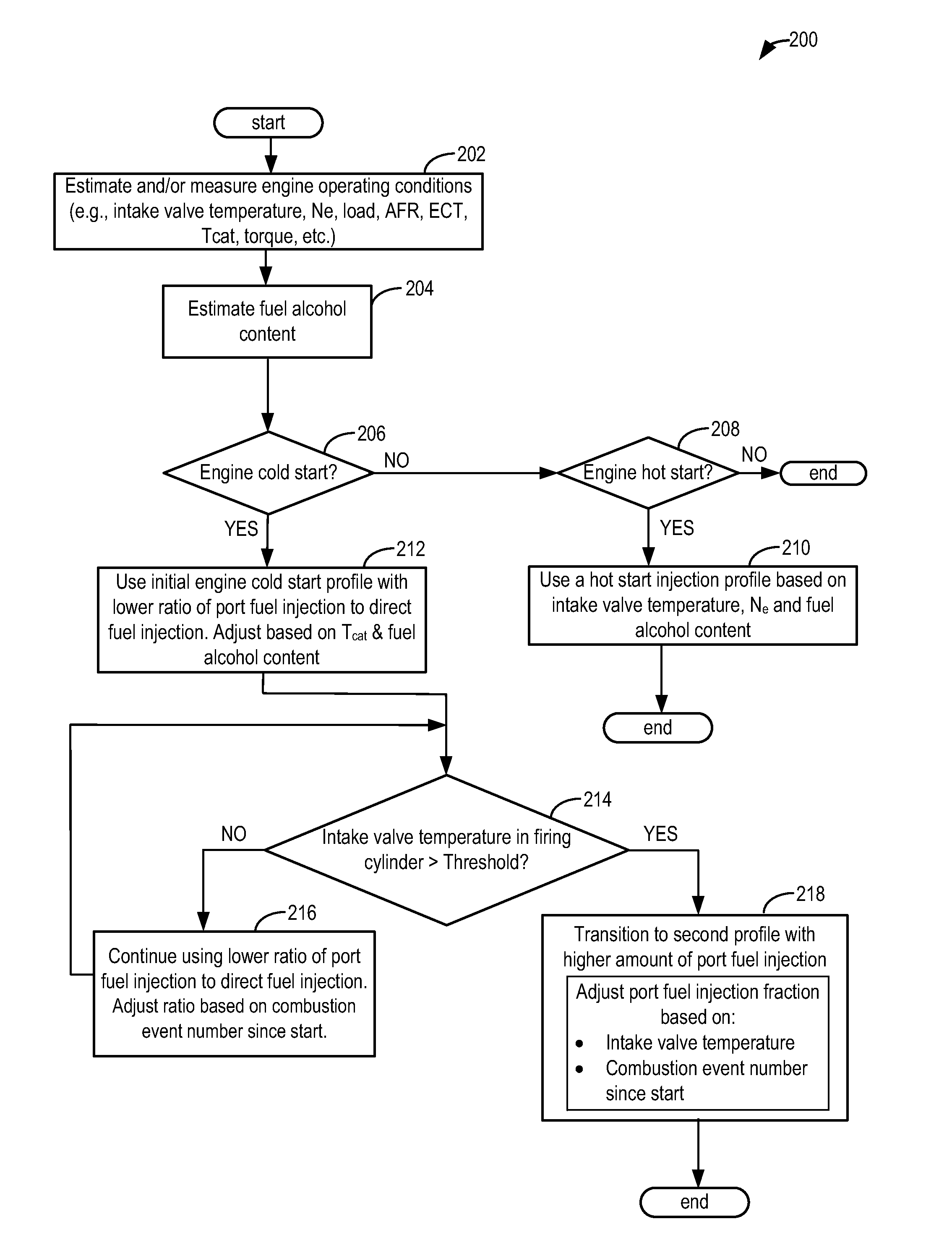
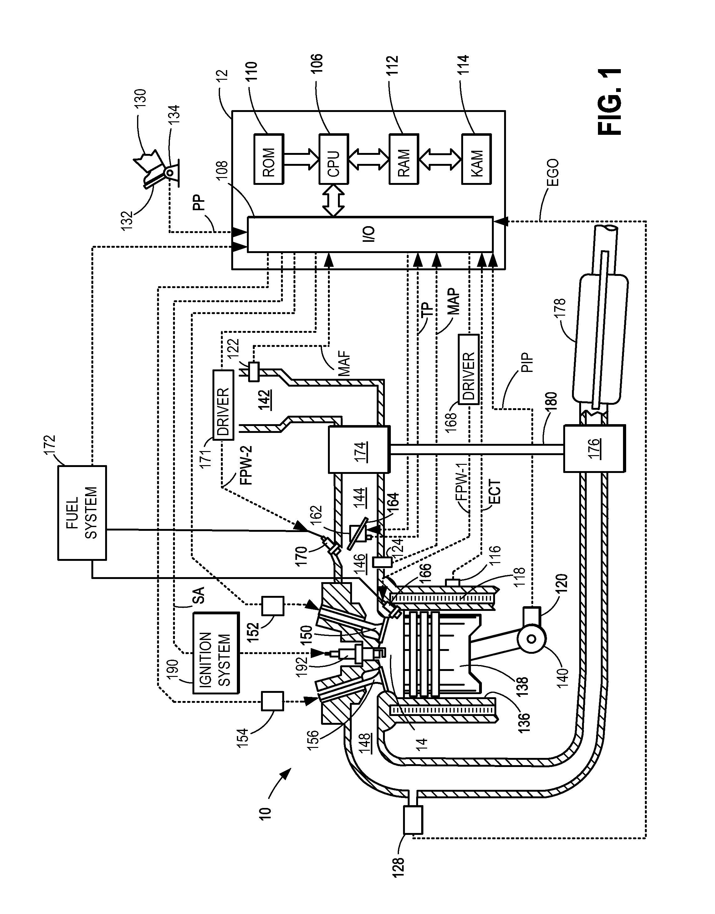
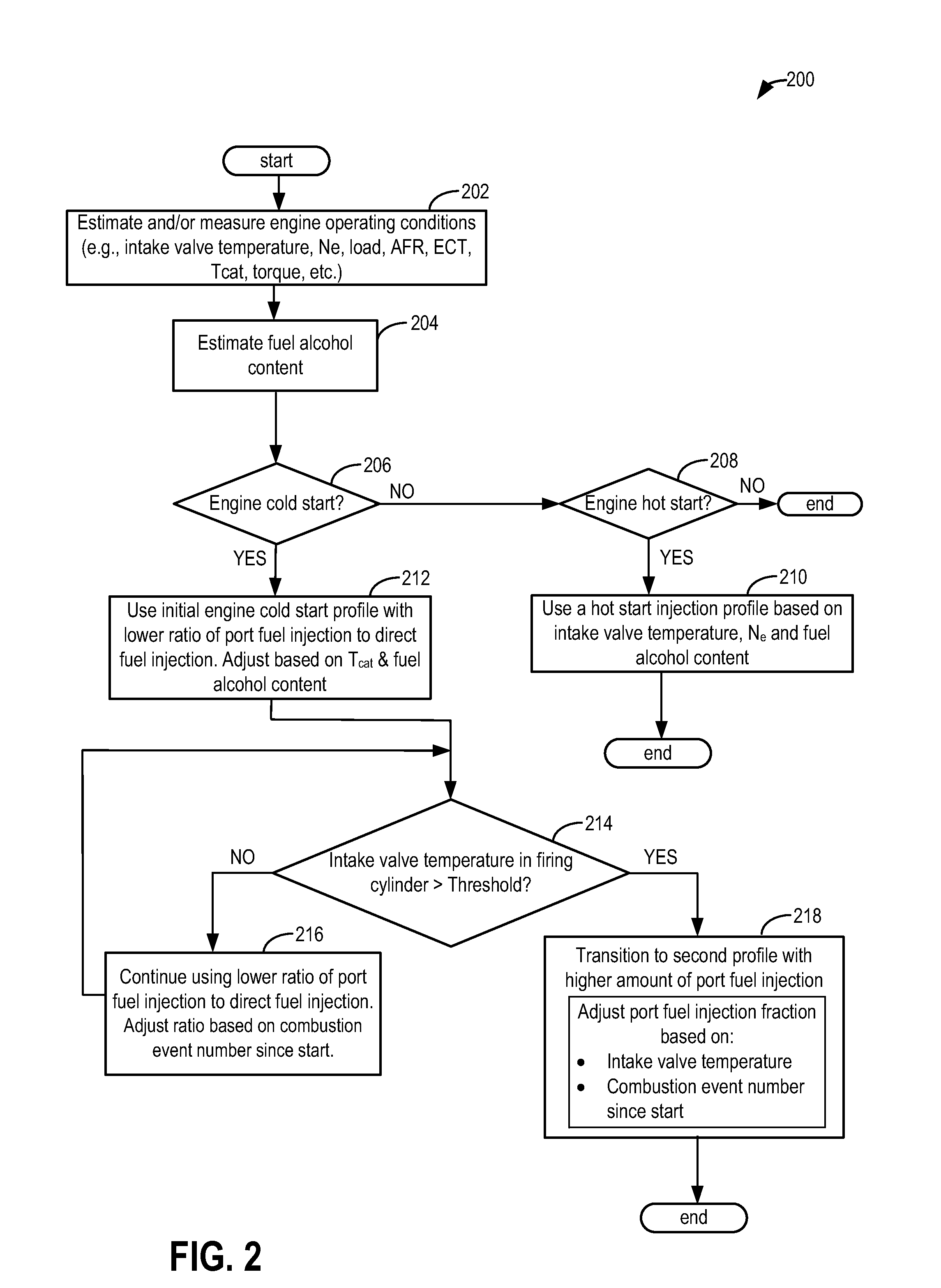
[0016]The following description relates to systems and methods for adjusting an engine fuel injection schedule, such as in the engine system of FIG. 1. An engine controller may adjust a fuel injection schedule, including an amount of fuel direct injected relative to an amount of fuel port injected into an engine cylinder, based on engine operating conditions including an intake valve temperature, as shown in the example routine of FIG. 2. As elaborated with reference to FIGS. 2-5, the adjustment may be based on combustion event number, exhaust catalyst temperature (e.g., hot start or cold start conditions), as well as intake valve temperature. For example, as intake valve temperature crosses a threshold, more fuel may be injected via port injection. By transitioning the fuel injection from a relatively higher amount of direct injection to a relatively higher amount of port injection as the intake valve temperature increases, as shown in FIG. 6, exhaust emissions may be controlled.

[0...


PUM


Abstract

Methods and systems are described for controlling fuel injection in an engine equipped with a dual injector system including a port injector and a direct injector. A ratio of port injected fuel to direct injected fuel is adjusted based at least on intake valve temperature. The proportion of fuel port injected into a cylinder is increased as the intake valve temperature for the given cylinder increases to improve fuel vaporization in the intake port.

Description

TECHNICAL FIELD[0001]The present application relates to methods and systems for controlling fuel injection in an engine system configured with both port and direct fuel injection.BACKGROUND AND SUMMARY[0002]Engines may be configured with direct fuel injectors that inject fuel directly into a combustion cylinder (direct injection), and / or with port fuel injectors that inject fuel into a cylinder intake port (port fuel injection). Direct injection (DI) offers higher fuel efficiency and higher power output in addition to enabling a charge cooling effect of the injected fuel. However, direct injected engines usually have higher particulate matter emissions (or soot) due to diffuse flame propagation wherein fuel may not adequately mix with air prior to combustion. Port fuel injection usually (PFI) provides cleaner emissions and high performance under low loads, due to improved mixing. In engine systems configured with each of a port injector and a direct injector coupled to each engine c...

Claims


Application Information

Patent Timeline
Patent Type & Authority Patents(United States)
IPC IPC(8): F02D41/30F02D41/06F02M69/30F02D41/04F02D19/08F02D13/02F02D41/00F02M45/00
CPCF02D41/3094F02D13/0207F02D13/0219F02D13/0261F02D19/084F02D19/088F02D41/0025F02D41/047F02D41/064F02D41/065F02M69/30F02D41/0007F02D41/008F02D2041/001F02D2200/021F02M45/00Y02T10/18Y02T10/36Y02T10/12Y02T10/30F02D41/3005F02D2200/04F02D2200/1002F02D2200/101
Inventor SURNILLA, GOPICHANDRAKRENGEL, ERICTHOMAS, JOSEPH LYLERUMPSA, TODD ANTHONYSHELBY, MICHAEL HOWARD
Owner FORD GLOBAL TECH LLC
Learn More