
Method and apparatus for sorting elements in hardware structures

a hardware structure and element technology, applied in the direction of concurrent instruction execution, instruments, computing, etc., can solve the problems of complexity that cannot be modified by, difficult to accurately restore the value of the element, and often added to the machine, so as to avoid the complexity of ordering elements, efficient and flexible

Active Publication Date: 2016-09-06
INTEL CORP
View PDF88 Cites 0 Cited by
  • Summary
  • Abstract
  • Description
  • Claims
  • Application Information

AI Technical Summary

Benefits of technology

This approach reduces computational and memory resource usage, eliminates the need for proximity constraints between the re-order buffer and register file, and simplifies the allocation process by deferring ordering until retirement, enhancing the efficiency and flexibility of the OOO processor architecture.

Problems solved by technology

However, in most cases, they are required to retire from the machine in order.
These diverging ordering behaviors give rise to problems at several locations in a micro-architecture.
As a result, complexity is often added to the machine, because element tagging and allocation needs to take place in all resources at the time of element allocation, e.g., the instruction allocation buffer also known as the “re-order buffer” (“ROB”) needs to perform tagging and allocation of resources at the time of instruction allocation.
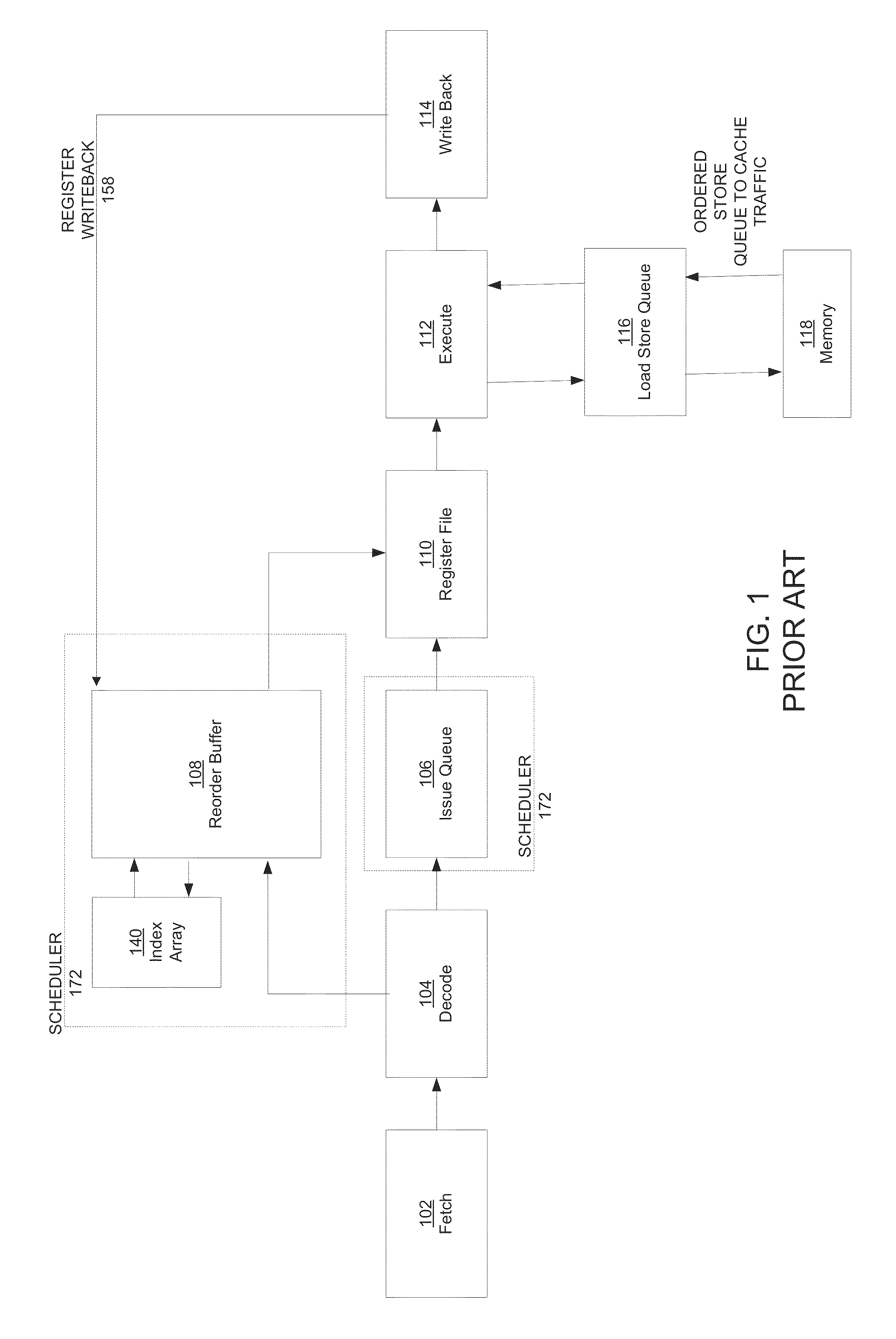
Because instructions may finish in an arbitrary order, the architectural register file 110 cannot be modified by the instructions as they finish because it would make it difficult to restore their values accurately in the event of an exception or an interrupt.
Further, additional communication overhead is required to tag all store instructions, to convey the tags along with the store instructions to the LSQ, and to communicate to the LSQ to add the store instructions to the locations designated by the respective tags.

Method used


Image

  • Method and apparatus for sorting elements in hardware structures
  • Method and apparatus for sorting elements in hardware structures
  • Method and apparatus for sorting elements in hardware structures

Examples


Embodiment Construction

[0027]Reference will now be made in detail to the various embodiments of the present disclosure, examples of which are illustrated in the accompanying drawings. While described in conjunction with these embodiments, it will be understood that they are not intended to limit the disclosure to these embodiments. On the contrary, the disclosure is intended to cover alternatives, modifications and equivalents, which may be included within the spirit and scope of the disclosure as defined by the appended claims. Furthermore, in the following detailed description of the present disclosure, numerous specific details are set forth in order to provide a thorough understanding of the present disclosure. However, it will be understood that the present disclosure may be practiced without these specific details. In other instances, well-known methods, procedures, components, and circuits have not been described in detail so as not to unnecessarily obscure aspects of the present disclosure.

Notatio...


PUM


Abstract

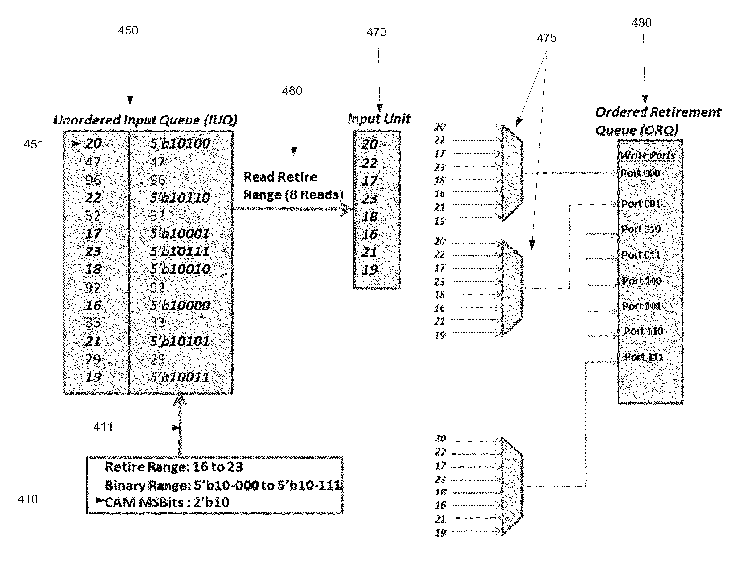
A method for sorting elements in hardware structures is disclosed. The method comprises selecting a plurality of elements to order from an unordered input queue (UIQ) within a predetermined range in response to finding a match between at least one most significant bit of the predetermined range and corresponding bits of a respective identifier associated with each of the plurality of elements. The method further comprises presenting each of the plurality of elements to a respective multiplexer. Further the method comprises generating a select signal for an enabled multiplexer in response to finding a match between at least one least significant bit of a respective identifier associated with each of the plurality of elements and a port number of the ordered queue. Finally, the method comprises forwarding a packet associated with a selected element identifier to a matching port number of the ordered queue from the enabled multiplexer.

Description

CROSS REFERENCE TO RELATED APPLICATIONS[0001]This application is a conversion of and claims priority to and the benefit of Provisional Patent Application No. 61 / 793,752, entitled “Method and Apparatus for Sorting Elements in Hardware Structures,” having a filing Date of Mar. 15, 2013, which is herein incorporated by reference in its entirety.FIELD OF THE INVENTION[0002]Embodiments according to the present invention generally relate to microprocessor architecture and more particularly to the architecture for out-of-order microprocessors.BACKGROUND OF THE INVENTION[0003]In an Out-Of-Order (“OOO”) microprocessor, instructions are allowed to issue out of their program order. However, in most cases, they are required to retire from the machine in order. Further, memory operations in the machine, regardless of the issue order, need to acquire and update memory status in program order. These diverging ordering behaviors give rise to problems at several locations in a micro-architecture. Fo...

Claims


Application Information

Patent Timeline
Patent Type & Authority Patents(United States)
IPC IPC(8): G06F9/30G06F9/38G06F9/40
CPCG06F9/3834G06F9/3855G06F9/3857G06F9/3858G06F9/3856G06F9/3854
Inventor ABDALLAH, MOHAMMAD A.SINGH, MANDEEP
Owner INTEL CORP
Learn More