Active vehicle suspension system and method for managing drive energy

a technology for active vehicles and suspensions, applied in the direction of resilient suspensions, vehicle components, transportation and packaging, etc., can solve the problem that the wheel becomes relatively difficult to travel forward, and achieve the effect of reducing the resisting effect, increasing the assisting effect, and reducing the vehicle drive energy

Active Publication Date: 2016-09-13
LACHICA SETH M
View PDF16 Cites 2 Cited by
  • Summary
  • Abstract
  • Description
  • Claims
  • Application Information

AI Technical Summary

Benefits of technology

[0017]Briefly, a presently preferred embodiment of the present invention provides a drive energy management and active suspension control system, and operative methodology, in which ground / pathway anomalies are sensed and used to enable or automatically effect adjustment of supporting actuators to reduce the resisting effects, and / or increase the assisting effects of the encountered ground / pathway anomalies, and thus reduce the vehicle drive energy that would otherwise be required to efficiently move the vehicle in the intended direction, yet maintain the stability of the vehicle.
[0018]Unlike a conventional spring suspension system in which an obstacle encountered by one wheel will cause a shift in the loads experienced by the springs associated with the other wheels but will not reduce the longitudinal motion resisting force experienced by the vehicle, in an active suspension system, the compression of the suspension components experienced by a wheel encountering an obstacle does not necessarily affect the magnitudes of the forces exerted by the several supporting actuators in supporting the vehicle, nor does it necessarily reduce the longitudinal motion resisting force experienced by the vehicle. However, in accordance with an embodiment of the present invention, when a particular wheel engages an obstacle, the resulting impediment to forward motion will be sensed and the force exerted by the actuator associated with the engaging wheel will be relaxed, resulting in a reduction of the forward motion resisting force experienced by the vehicle, and in order to maintain the stability of the vehicle, the supporting forces exerted by the other actuators will also be adjusted.
[0019]For example, in accordance with the present invention, with the right front wheel of the vehicle engaging and traveling up a rock, the computerized suspension control system will sense the condition and cause a reduction in the downward force on that wheel resulting in less drive energy needed to move that wheel forward. The computer looks at the actuators supporting the other three wheels and makes corresponding adjustments to the exerted downward forces to maintain the stability of the vehicle. These adjustments might even include purposefully increasing the downward forces exerted on wheels that have negative angles of approach for the purpose of taking advantage of the “downhill roll”. This is to say that a large downward force applied to a wheel with a negative angle of approach will act to assist forward movement and reduce the overall drive energy required to move the vehicle forward.
[0021]An advantage of the present invention is that it provides an active suspension system and method which senses each wheel's positive or negative angle of approach to roadway or ground / pathway anomalies, and uses the sensed information to make appropriate actuator force adjustments and thus indirectly “manage” vehicle drive energy requirements.
[0022]Another advantage of the present invention is that it provides an active suspension system and method which determines actuator force combinations that can be used at all four wheels without upsetting the chassis and causing unwonted chassis movements that may otherwise result from the actuator force adjustments.
[0023]Still another advantage of the present invention is that it uses a computer processor to process detected information relating to encountered obstacles or other ground / pathway anomalies, and to balance and adjust the forces applied by the several suspension actuators in a manner that will reduce the amount of prime mover drive energy otherwise required to move the vehicle forward while maintaining vehicle stability and ride control.

Problems solved by technology

It is easy to see that in this scenario it becomes relatively difficult for this wheel to travel forward.

Method used


Image

  • Active vehicle suspension system and method for managing drive energy
  • Active vehicle suspension system and method for managing drive energy
  • Active vehicle suspension system and method for managing drive energy

Examples


Embodiment Construction

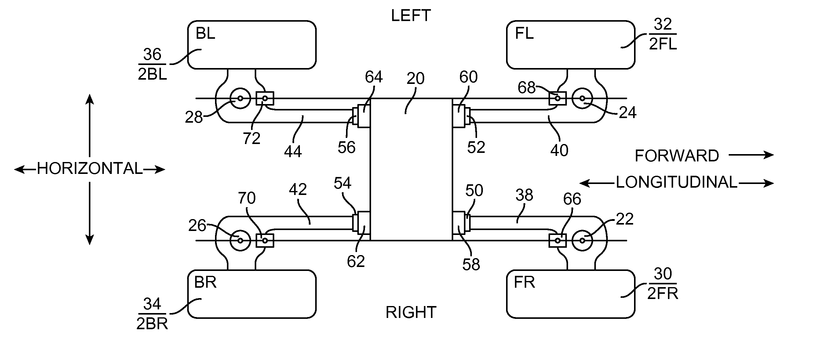
[0033]By way of introduction, the present invention may be generally characterized as an active drive energy management and suspension system for a vehicle having a vehicle chassis supported above at least four ground / pathway engaging vehicle wheels, the system comprising inter alia: a plurality of actuators, each capable of exerting a variable supporting force between an associated vehicle wheel and the vehicle chassis; means for determining the slope of the ground / pathway relative to the vehicle chassis in the direction of vehicle movement at the points of contact between each vehicle wheel and the ground / pathway, and for generating corresponding slope signals; and control means responsive to the inter relationships of the respective slope signals and operative to determine therefrom an engagement of a ground / pathway anomaly acting as an impediment or assistant to forward motion of the vehicle, and to cause a first set of the actuators associated with a first set of diametrically ...


PUM


Abstract

A vehicle drive energy management and active suspension control system and operative methodology in which ground / pathway anomalies are sensed and the relationship thereof to the vehicle chassis is used to enable or automatically effect adjustment of chassis supporting actuators to reduce resisting effects and / or increase assisting effects of the encountered ground / pathway anomalies and thus reduce the vehicle drive energy that would otherwise be required to efficiently move the vehicle in the intended direction, yet maintain the stability of the vehicle.

Description

BACKGROUND OF THE INVENTION[0001]1. Field of the Invention[0002]The present invention relates generally to active vehicle suspension systems and more particularly to a system and method for enhancing an active vehicle suspension system by sensing the engagement of obstacles or uneven ground and adjusting the suspending actuator forces to reduce the amount of drive energy otherwise required to overcome the ground / pathway anomaly and move the vehicle forward while at the same time maintaining the stability of the vehicle.[0003]2. Description of the Prior Art[0004]In conventional vehicle suspension systems various types of springs and associated shock absorbing devices have historically been the primary components used to exert supporting forces between the chassis and wheels in order to provide vehicle stability and ride comfort. More recently, active and partially active (hybrid) suspension systems include actuators controlled by a microprocessor to provide these forces.[0005]The ben...

Claims


Application Information

Patent Timeline
Patent Type & Authority Patents(United States)
IPC IPC(8): B60G17/0185B60G17/018B60G17/0165B60G17/019
CPCB60G17/0165B60G17/0182B60G17/01941B60G2600/182B60G2600/73B60G2400/204B60G2400/252
Inventor LACHICA, SETH M.
Owner LACHICA SETH M
Why Eureka
Try Eureka