
Ligation clip with flexible clamping feature

a flexible and clip technology, applied in the field of surgical clips, can solve the problems of limited space and visibility, time-consuming and difficult to perform complex manipulations of surgical threads, and complex manipulations that require complex needle manipulations, so as to improve the area of tissue being retained, improve the clamping and retention of the vessel, and improve the effect of safety

Active Publication Date: 2016-09-20
TELEFLEX MEDICAL INC
View PDF78 Cites 101 Cited by
  • Summary
  • Abstract
  • Description
  • Claims
  • Application Information

AI Technical Summary

Benefits of technology

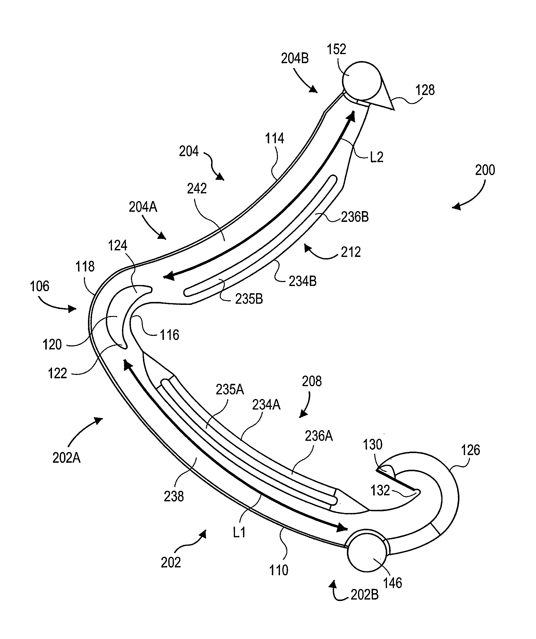
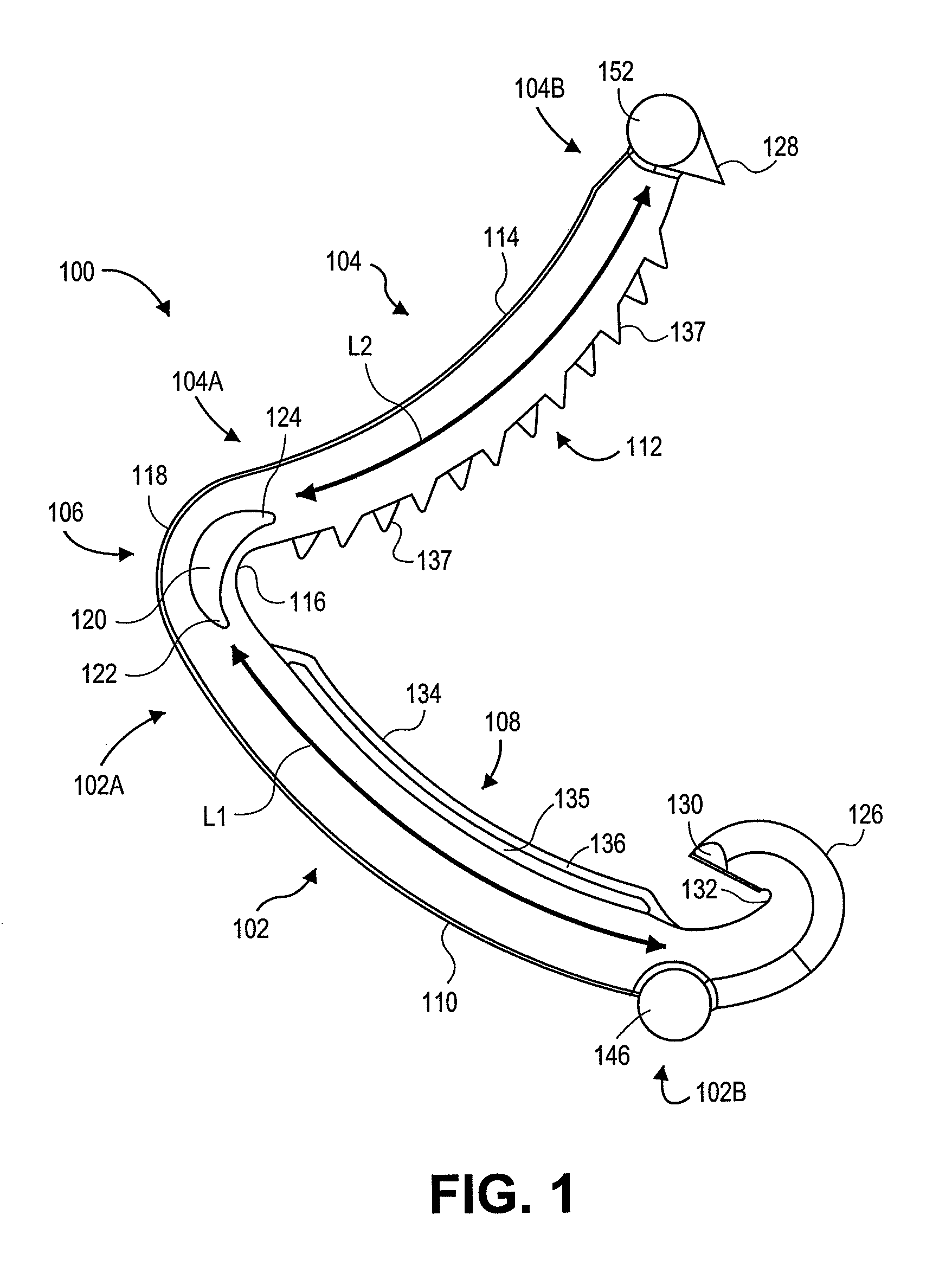
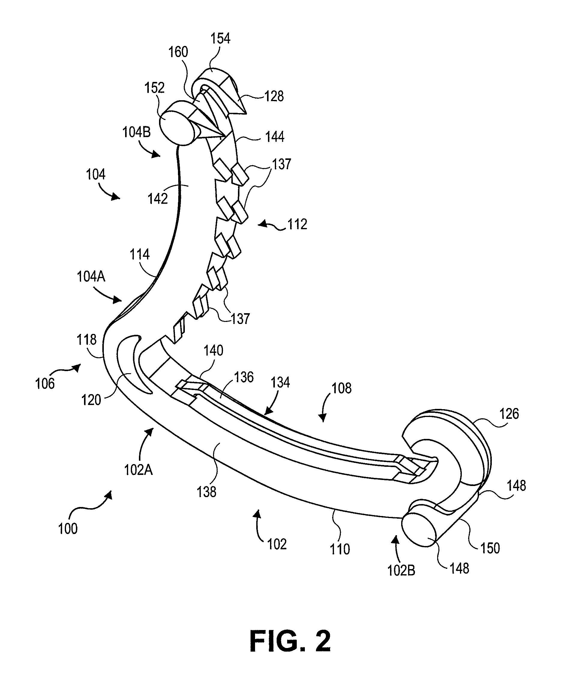
The present invention provides a ligation clip with a flexible collapsible rib that improves clamping and retention of the clip on a vessel. The rib can be on one or both legs of the clip and has teeth that interlock with protrusions on the other leg, providing better vessel clamping and retention. The clip can apply additional pressure on the vessel tissue through a cross-clamping action, increasing the area of tissue being retained.

Problems solved by technology

The use of surgical thread for ligation requires complex manipulations of the needle and suture material to form the knots required to secure the vessel.
Such complex manipulations are time-consuming and difficult to perform, particularly in endoscopic surgical procedures, which are characterized by limited space and visibility.
But, with the advent of high technology diagnostic techniques using computer tomography (CATSCAN) and magnetic resonance imaging (MRI), metallic clips have been found to interfere with the imaging techniques.
Although plastic ligating clips are well known in the surgical area and improvements have been made to the ligating clips, including providing protrusions on the inner surfaces of the leg members to impede the lateral movement of a vessel during clip closure (see, for example, the aforementioned U.S. Pat. Nos. 4,834,096 and 5,062,846), these improvements have been less effective in preventing movement of the clip along the length of a vessel or tissue during and after clip closure.
The occlusion of the vessel by a ligating clip can accidentally damage the vessel or severe it.

Method used


Image

  • Ligation clip with flexible clamping feature
  • Ligation clip with flexible clamping feature
  • Ligation clip with flexible clamping feature

Examples


Embodiment Construction

[0023]The invention will now be described with reference to the drawing figures, in which like reference numerals refer to like parts throughout. In accordance with conventional practice, as used herein, and unless otherwise indicated herein, the term “proximal” or “proximal end” shall refer to the specified end of a device or its component which is generally closer to the medical personnel handling or manipulating the device as it is intended to be used, and the term “distal” or “distal end” shall refer to the specified end of a device or its component which is opposite the proximal end.

[0024]The present invention involves a surgical ligating clip, preferably made of a polymeric material, which can be used to clamp vessels such as arteries in the body, having a pair of asymmetric, curved concave-convex legs, and including one or more flexible rib portions as well as rows of protruding teeth to provide an improved and superior interlocking means to retain the clip on a vessel. The s...


PUM


Abstract

A polymeric surgical ligating clip is provided having curved leg members joined by a resilient hinge. A leg member includes a flexible rib protruding from a vessel clamping inner surface and extends longitudinally between the proximal and distal end portions of the leg member. The flexible rib defines a channel extending transversely through the rib along a majority of said length. The flexible rib can collapse and provides better retention of the clip on a vessel. The clip can contain a flexible rib on both legs in an interlocking fashion. Or a plurality of teeth can protrude from a second vessel clamping inner surface of a second leg member. The plurality of teeth can include first and second rows of teeth extending longitudinally on the second leg member, transversely separated from each other on opposite sides of a centerline of the clip.

Description

CROSS-REFERENCE TO RELATED APPLICATIONS[0001]None.FIELD OF THE INVENTION[0002]The present invention relates to medical devices and in particular surgical clips for ligation of vessels or tissue.BACKGROUND OF THE INVENTION[0003]Many surgical procedures require vessels or other tissues of the human body to be ligated during the surgical process. For example, many surgical procedures require cutting blood vessels (e.g., veins or arteries), and these blood vessels may require ligation to reduce bleeding. In some instances, a surgeon may wish to ligate the vessel temporarily to reduce blood flow to the surgical site during the surgical procedure. In other instances a surgeon may wish to permanently ligate a vessel. Ligation of vessels or other tissues can be performed by closing the vessel with a ligating clip, or by suturing the vessel with surgical thread. The use of surgical thread for ligation requires complex manipulations of the needle and suture material to form the knots required...

Claims


Application Information

Patent Timeline
Patent Type & Authority Patents(United States)
IPC IPC(8): A61B17/08A61B17/122A61B17/00
CPCA61B17/122A61B2017/00862
Inventor WHITING, PAUL E.
Owner TELEFLEX MEDICAL INC
Learn More