Check patentability & draft patents in minutes with Patsnap Eureka AI!

Double-walled turbocharger housing, flange and connection thereof

a turbocharger and housing technology, applied in the direction of liquid fuel engines, motors, mechanical equipment, etc., can solve the problems of destroying the turbocharger, the welding seam is not strong enough to withstand the stresses, and the connection of the double walled turbocharger in question here is not possible, so as to improve the tension distribution and affect the durability of the common shell connection and welding seam

Active Publication Date: 2016-09-20
BENTELER AUTOMOBILTECHNIK GMBH
View PDF22 Cites 7 Cited by
  • Summary
  • Abstract
  • Description
  • Claims
  • Application Information

AI Technical Summary

Benefits of technology

This patent describes a design for a turbocharger housing that prevents heat from damaging the outer shell of the housing. A gap between the inner and outer shells of the housing creates a barrier, reducing heat transfer by up to 800°C. The design also allows for independent expansion of the inner and outer shells, ensuring durability and a better tension distribution.

Problems solved by technology

During operation, especially the impeller housing is exposed to high thermal stresses i.e., temperature gradients of more than 800° C. The relatively brittle welding seam is not capable to withstand the stresses during continuous operation.
In addition, welding spatter in the impeller housing can destroy the turbocharger which necessitates an extremely thorough post processing of the impeller housing.
A connection of the double walled turbocharger housing in question here is not possible however, because the inner sheet metal shell which conducts hot exhaust gases would jam as a result of contact with the relatively cold outer sheet metal shell during operation due to the heat expansion and as a result would permanently shear off.

Method used


Image

  • Double-walled turbocharger housing, flange and connection thereof
  • Double-walled turbocharger housing, flange and connection thereof
  • Double-walled turbocharger housing, flange and connection thereof

Examples


Embodiment Construction

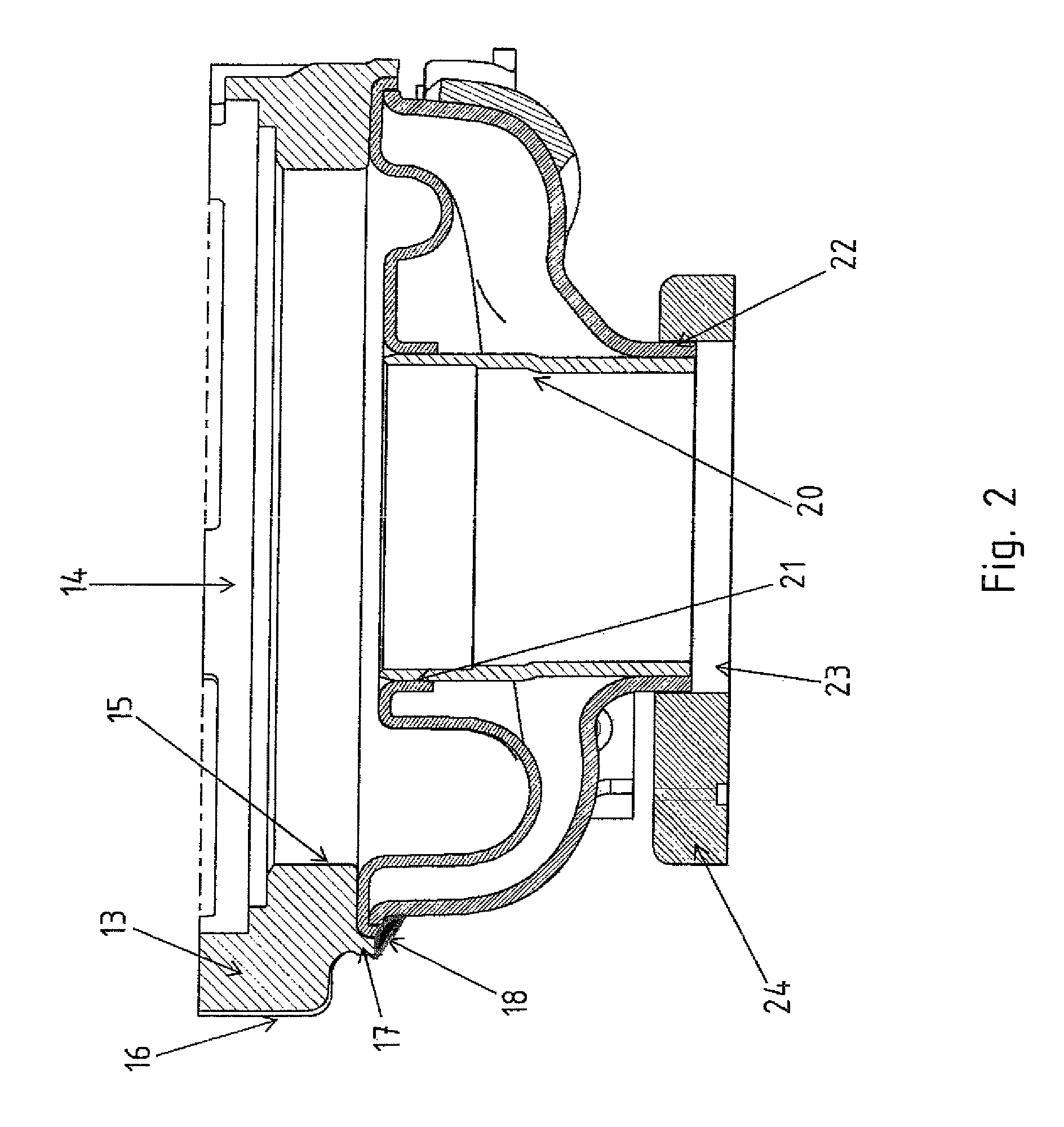
[0018]Throughout all the Figures, same or corresponding elements are generally indicated by same reference numerals. These depicted embodiments are to be understood as illustrative of the invention and not as limiting in any way. It should also be understood that the drawings are not necessarily to scale and that the embodiments are sometimes illustrated by graphic symbols, phantom lines, diagrammatic representations and fragmentary views. In certain instances, details which are not necessary for an understanding of the present invention or which render other details difficult to perceive may have been omitted.

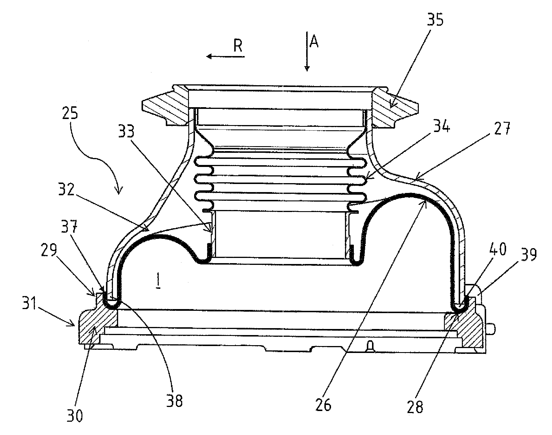
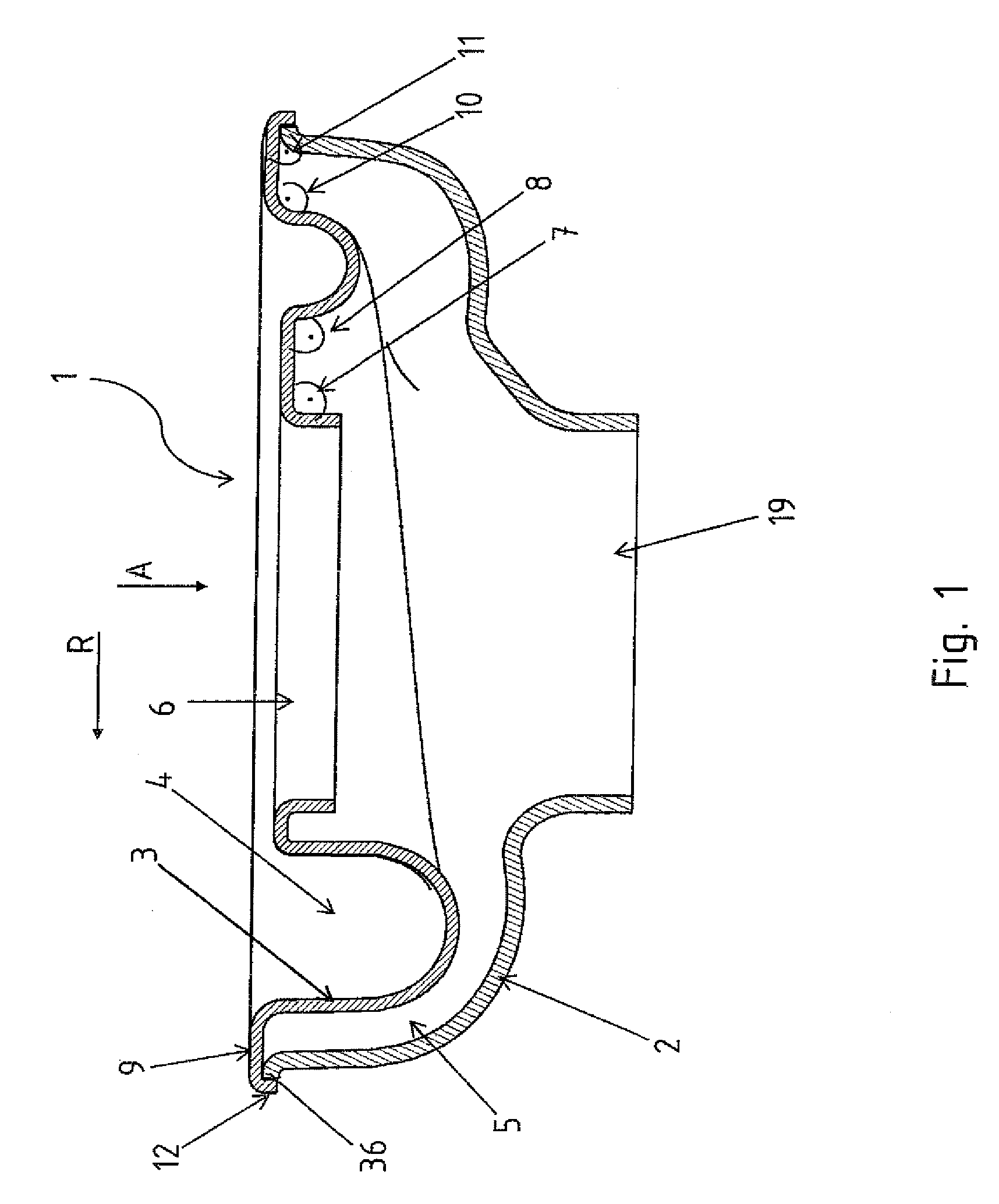
[0019]Turning now to the drawing, and in particular to FIG. 1, there is shown a sectional view of a double walled turbocharger housing 1 according to the invention. Only an outer sheet metal shell 2 and an inner sheet metal shell 3 are shown. The inner sheet metal shell 3 forms a gas channel 4 in which hot exhaust gas flows during operation. The outer sheet metal shell 2 is sp...


PUM

PropertyMeasurementUnit
widthaaaaaaaaaa
temperatureaaaaaaaaaa
temperaturesaaaaaaaaaa

Abstract

A double-walled turbocharger housing made of sheet metal includes an inner sheet metal shell which conducts hot exhaust gases and a relatively cold outer sheet metal shell which is spaced apart from the inner sheet metal shell via an air gap. The double-walled turbocharger housing is connected to a bearing flange with a circumferential collar via a common welding seam. The bearing flange is provided with a collar on an outside which faces away from the hot exhaust gas. An outer end of the inner sheet metal shell is provided with a collar with which it embraces the outer sheet metal shell. Both sheet metal shells are connected with the collar of the bearing flange via a common welding seam, wherein an air gap is present between the inner sheet metal shell and the outer sheet metal shell up to the outer end of the inner sheet metal shell.

Description

CROSS-REFERENCES TO RELATED APPLICATIONS[0001]This application claims the priority of German Patent Application, Serial No. 10 2012 009 090.0, filed May 9, 2012, pursuant to 35 U.S.C. 119(a)-(d), the disclosure of which is incorporated herein by reference.BACKGROUND OF THE INVENTION[0002]The present invention relates to a connection of a double walled turbocharger housing made of sheet metal with an inner sheet metal shell which conducts hot-exhaust gases and a cold outer sheet metal shell which is spaced apart from the inner sheet metal shell to a flange with a circumferential collar via a common welding seam.[0003]The following discussion of related art is provided to assist the reader in understanding the advantages of the invention, and is not to be construed as an admission that this related art is prior art to this invention.[0004]A connection of the generic type is known from DE 100 22 052 A1. This printed publication discloses in particular in FIG. 5 a double walled turbocha...

Claims


Application Information

Patent Timeline
Patent Type & Authority Patents(United States)
IPC IPC(8): F01D25/26F01D25/24F02C6/12F01D25/06
CPCF01D25/06F01D25/243F02C6/12Y10T29/49323F01D25/26F05D2230/232
Inventor GRUSSMANN, ELMARLESCH, ARTHUR
Owner BENTELER AUTOMOBILTECHNIK GMBH
Features
  • R&D
  • Intellectual Property
  • Life Sciences
  • Materials
  • Tech Scout
  • Unparalleled Data Quality
  • Higher Quality Content
  • 60% Fewer Hallucinations
Learn More