Non-reciprocal circuit element

a circuit element and non-reciprocal technology, applied in the direction of impedence networks, multiple-port networks, electrical apparatus, etc., can solve the problems of reducing the freedom with which the various parameters can be set, difficult to achieve a desired inductance, and so as to avoid drastic drop in inductance, avoid drastic drop in coupling, and reduce the combined inductance of the second center electrode

Active Publication Date: 2015-03-12
MURATA MFG CO LTD
View PDF0 Cites 0 Cited by
  • Summary
  • Abstract
  • Description
  • Claims
  • Application Information

AI Technical Summary

Benefits of technology

[0010]Accordingly, preferred embodiments of the present invention provide a non-reciprocal circuit element configured to operate in a high-frequency band by reducing the inductance of a second center electrode without negatively affecting the rest of the element.
[0012]In the non-reciprocal circuit element, the sub-center electrode is connected in parallel to a portion of the second center electrode, and thus the combined inductance of the second center electrode is reduced. In other words, by setting the inductance of the sub-center electrode to an appropriate value, the inductance of the second center electrode is capable of being adjusted by fine amounts, which makes it possible to avoid drastic drops in the inductance as when reducing the number of times the electrodes are wrapped and obtaining a desired inductance as a result. This avoids a drop in the coupling between the first and second center electrodes, which in turn prevents the insertion loss characteristics from degrading. In addition, it is not necessary to increase the line width of the second center electrode, to increase the depth of the through-holes, or to make the ferrite thinner, which makes it possible to avoid the risk of shorts between the electrodes and avoid breaks, cracks and so on from being produced in the ferrite substrate.
[0013]According to various preferred embodiments of the present invention, the inductance of the second center electrode is significantly reduced without negatively affecting the rest of the element, which makes it possible to operate in a high-frequency band.

Problems solved by technology

However, reducing the size of the isolator also makes it necessary to reduce the size of the ferrite, which in turn reduces the freedom with which the various parameters can be set, making it difficult to achieve a desired inductance.
However, reducing the number of times the electrodes are wrapped will cause a drastic drop in the inductance.
The coupling of the first and second center electrodes will also drop, causing a degradation in the insertion loss characteristics.
Meanwhile, increasing the line width of the center electrodes or increasing the depth of the through holes results in an increased chance of shorts between the electrodes, which is problematic in terms of reliability.
Furthermore, reducing the thickness of the ferrite is problematic because doing so also reduces the strength of the ferrite, which in turn increases the chance of breaks, cracks, and so on being produced in a ferrite substrate during a polishing process, a process for forming the center electrodes, and so on.
In such a case, the optimal inductance for the center electrodes is low, and thus the aforementioned problems appear prominently.
Furthermore, inter-line stray capacitance is generated unavoidably between the center electrodes, resulting in the center electrodes self-resonating at a constant frequency, and thus a non-reciprocal circuit element that operates at a frequency band greater than or equal to the self-resonating frequency cannot be realized.

Method used


Image

  • Non-reciprocal circuit element
  • Non-reciprocal circuit element
  • Non-reciprocal circuit element

Examples


first preferred embodiment

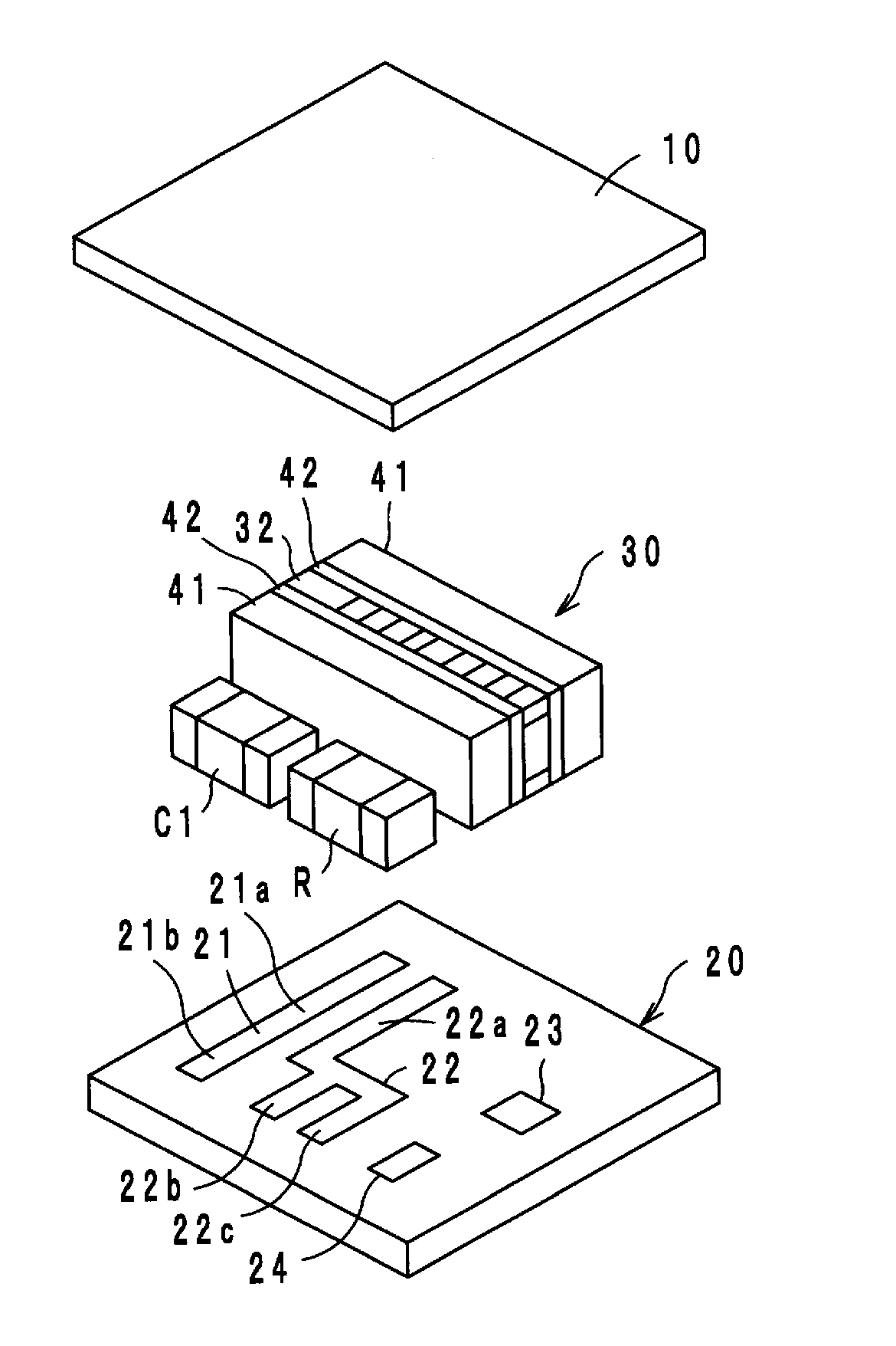
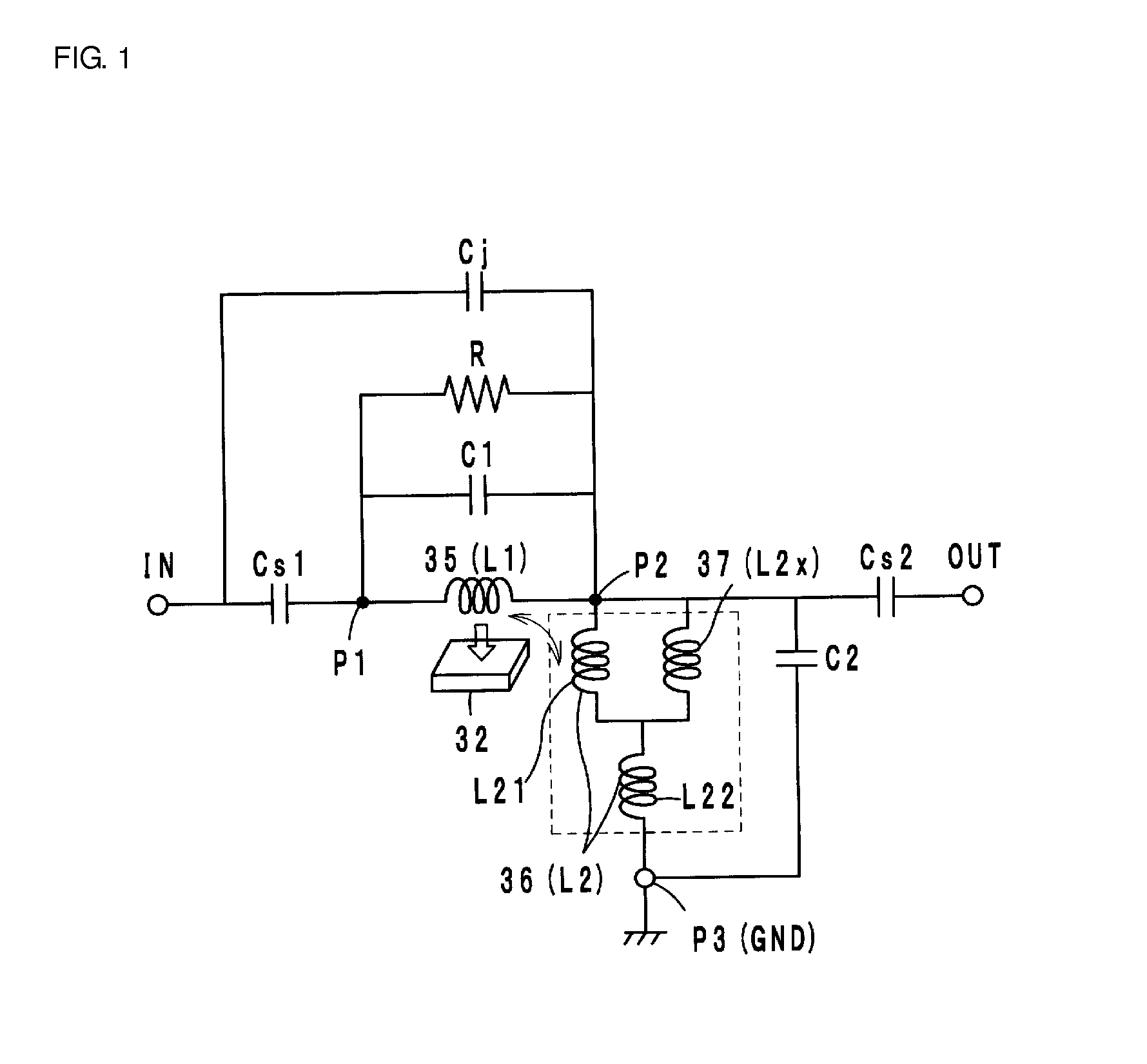
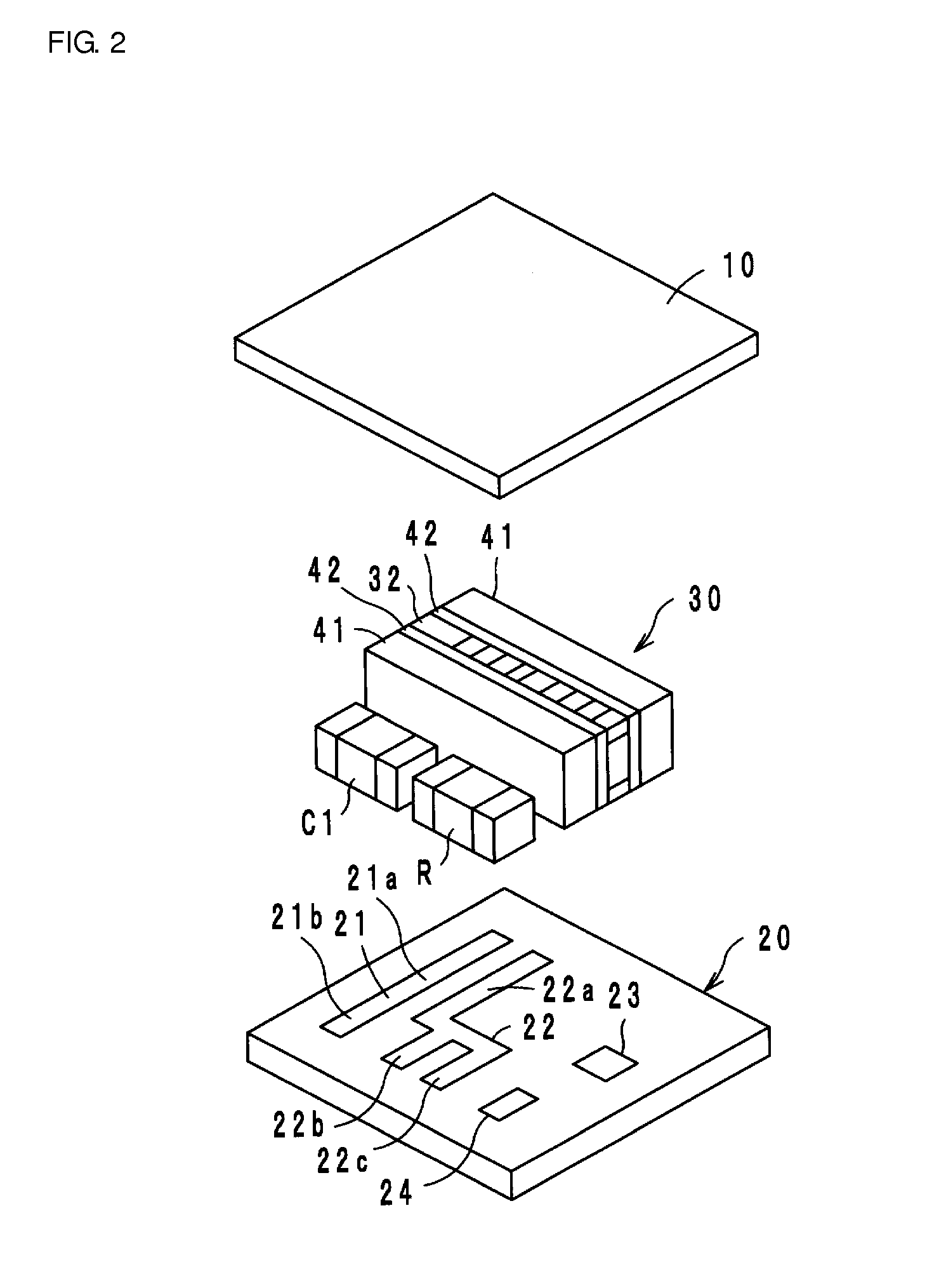
[0022]A two-port isolator according to a first preferred embodiment is preferably configured as an equivalent circuit illustrated in FIG. 1. That is, the isolator includes a microwave magnetic body (called a ferrite 32 hereinafter) to which a direct current magnetic field is applied by a permanent magnet not shown here, and a first center electrode 35 (an inductance L1) and a second center electrode 36 (an inductance L2) disposed so as to intersect around the ferrite 32 and be electrically insulated from each other. The first center electrode 35 is connected at one end to an input port P1 and at the other end to an output port P2. The second center electrode is connected at one end to the output port P2 and at the other end to a ground port P3. A terminating resistance R is connected between the input port P1 and the output port P2 in parallel with the first center electrode 35, a matching capacitor C1 is connected between the input port P1 and the output port P2, and a matching cap...

second preferred embodiment

[0040]In a two-port isolator according to the second preferred embodiment of the present invention, a path length of the sub-center electrode 37 connected to the electrodes 36a and 36c of the second center electrode 36 in parallel is preferably slightly longer than that in the sub-center electrode 37 according to the first preferred embodiment, as shown in FIG. 4. Other configurations are preferably the same or substantially the same as in the first preferred embodiment.

[0041]In the present second preferred embodiment, increasing the path length of the sub-center electrode 37 sets the inductance L2x of the sub-center electrode 37 to be slightly higher than the inductance L21 of the parallel portion of the second center electrode 36. Specifically, the inductance L21 is preferably set to about 1.0 nH, the inductance L2x is preferably set to about 2.0 nH, and the inductance L22 is preferably set to about 3.0 nH, for example. The combined inductance L2 preferably is about 3.7 nH, for ex...

third preferred embodiment

[0042]In a two-port isolator according to the third preferred embodiment of the present invention, a ferrite 132 is configured of a multilayer body obtained by stacking sheets 132a to 132e in order and firing the sheets, and first and second center electrodes 135 and 136, as well as a sub-center electrode 137, are provided on front and rear surfaces and within the ferrite 132, as indicated in FIG. 6.

[0043]Specifically, the first center electrode 135 is formed preferably by connecting an electrode 135a to one end of an electrode 135c through a via hole conductor 135b, connecting the other end of the electrode 135c to one end of an electrode 135e through a via hole conductor 135d, connecting the other end of the electrode 135e to one end of an electrode 135g through a via hole conductor 135f, and connecting the other end of the electrode 135g to an electrode 135i through a via hole conductor 135h. The electrode 135a is connected to an electrode 135k (the input port P1) through a via h...


PUM


Abstract

A non-reciprocal circuit element includes a permanent magnet, a microwave magnetic body to which a direct current magnetic field is applied by the permanent magnet, a first center electrode that is wrapped around the microwave magnetic body, is connected at one end to an input port, and is connected at another end to an output port, a second center electrode that is wrapped around the microwave magnetic body while intersecting with the first center electrode so as to be insulated from the first center electrode, is connected at one end to the output port, and is connected at another end to a ground port, a first matching capacitance connected between the input port and the output port in parallel with the first center electrode, a terminating resistance connected between the input port and the output port in parallel with the first center electrode, and a second matching capacitance connected between the output port and the ground port. A sub-center electrode is connected in parallel to a portion of the second center electrode.

Description

BACKGROUND OF THE INVENTION[0001]1. Field of the Invention[0002]The present invention relates to non-reciprocal circuit elements, and particularly relates to non-reciprocal circuit elements such as isolators, circulators, and the like, preferably for use in microwave bands, for example.[0003]2. Description of the Related Art[0004]Non-reciprocal circuit elements such as isolators, circulators, and the like have conventionally had characteristics in which signals are transmitted only in a predetermined specific direction, and are not transmitted in the reverse direction. Using such characteristics, an isolator, for example, is used as a sending circuit portion in a mobile communication device such as a cellular phone or the like.[0005]As this type of non-reciprocal circuit element, WO 2008 / 087782 discloses a two-port isolator configured of a permanent magnet, a ferrite to which a direct current magnetic field is applied by the permanent magnet, a first center electrode and a second ce...

Claims


Application Information

Patent Timeline
Patent Type & Authority Applications(United States)
IPC IPC(8): H01P1/36H03H7/38
CPCH01P1/36H01P1/365H03H7/38H03H7/52
Inventor HINO, SEIGO
Owner MURATA MFG CO LTD
Why Eureka
Try Eureka