Non-reciprocal circuit element
a circuit element and non-reciprocal technology, applied in the direction of impedence networks, multiple-port networks, electrical apparatus, etc., can solve the problems of reducing the freedom with which the various parameters can be set, difficult to achieve a desired inductance, and so as to avoid drastic drop in inductance, avoid drastic drop in coupling, and reduce the combined inductance of the second center electrode
- Summary
- Abstract
- Description
- Claims
- Application Information
AI Technical Summary
Benefits of technology
Problems solved by technology
Method used
Image
Examples
first preferred embodiment
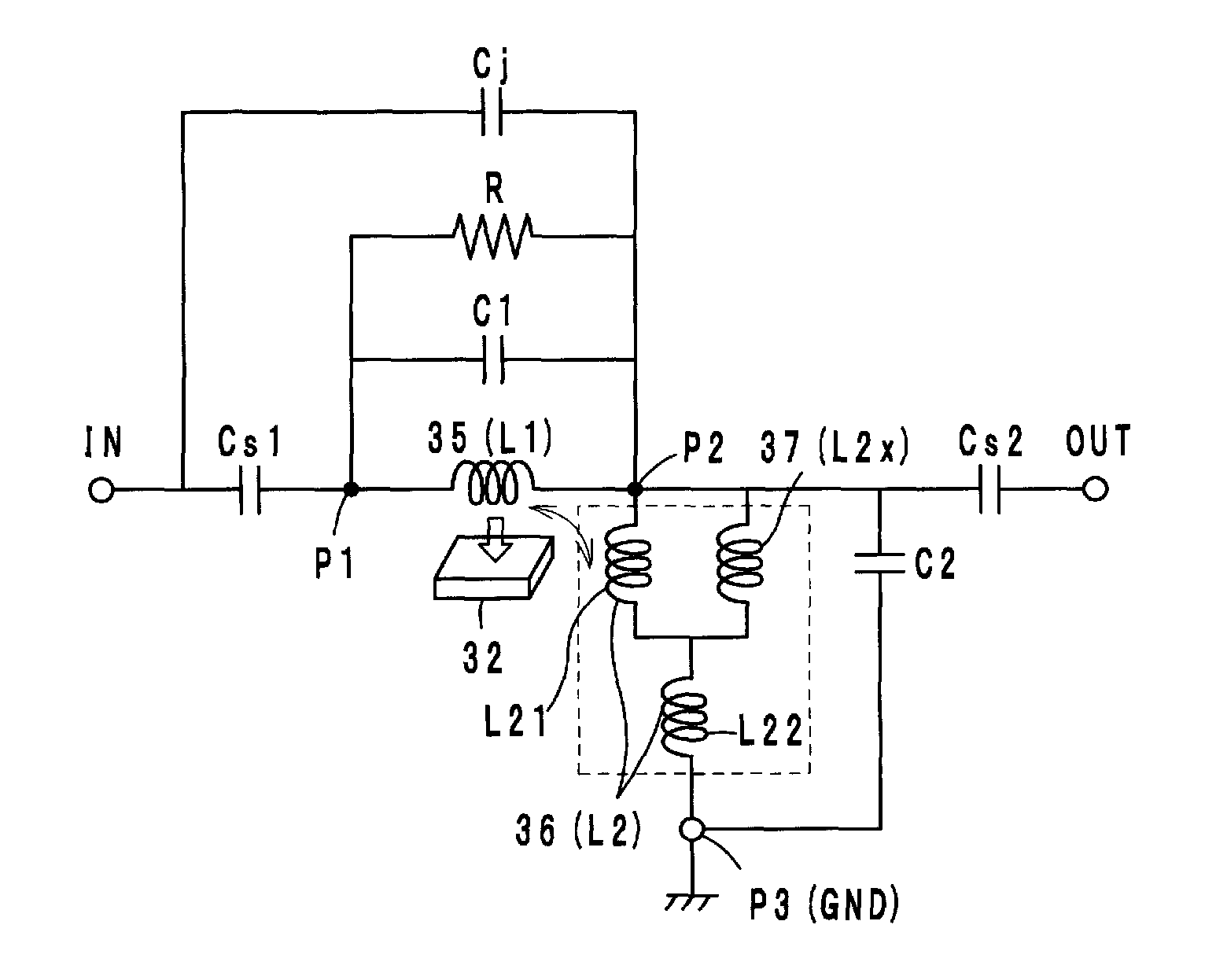
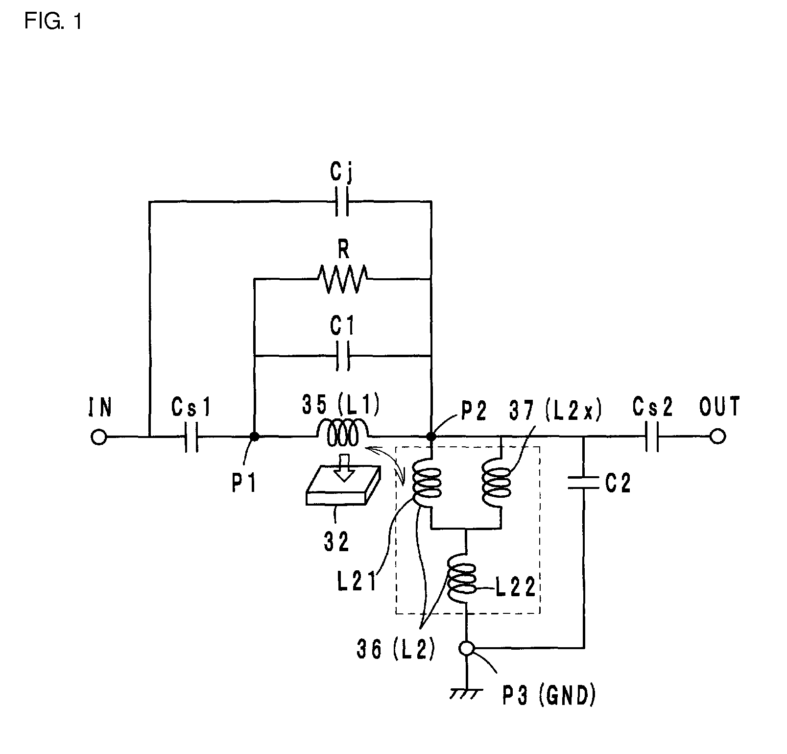
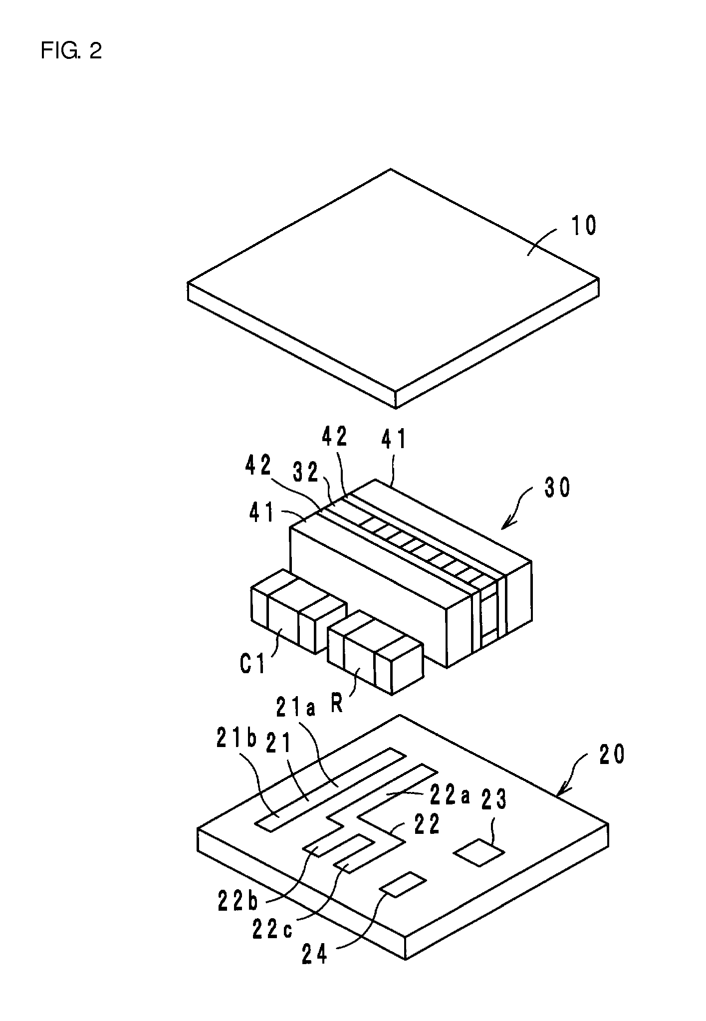
[0022]A two-port isolator according to a first preferred embodiment is preferably configured as an equivalent circuit illustrated in FIG. 1. That is, the isolator includes a microwave magnetic body (called a ferrite 32 hereinafter) to which a direct current magnetic field is applied by a permanent magnet not shown here, and a first center electrode 35 (an inductance L1) and a second center electrode 36 (an inductance L2) disposed so as to intersect around the ferrite 32 and be electrically insulated from each other. The first center electrode 35 is connected at one end to an input port P1 and at the other end to an output port P2. The second center electrode is connected at one end to the output port P2 and at the other end to a ground port P3. A terminating resistance R is connected between the input port P1 and the output port P2 in parallel with the first center electrode 35, a matching capacitor C1 is connected between the input port P1 and the output port P2, and a matching cap...
second preferred embodiment
[0040]In a two-port isolator according to the second preferred embodiment of the present invention, a path length of the sub-center electrode 37 connected to the electrodes 36a and 36c of the second center electrode 36 in parallel is preferably slightly longer than that in the sub-center electrode 37 according to the first preferred embodiment, as shown in FIG. 4. Other configurations are preferably the same or substantially the same as in the first preferred embodiment.
[0041]In the present second preferred embodiment, increasing the path length of the sub-center electrode 37 sets the inductance L2x of the sub-center electrode 37 to be slightly higher than the inductance L21 of the parallel portion of the second center electrode 36. Specifically, the inductance L21 is preferably set to about 1.0 nH, the inductance L2x is preferably set to about 2.0 nH, and the inductance L22 is preferably set to about 3.0 nH, for example. The combined inductance L2 preferably is about 3.7 nH, for ex...
third preferred embodiment
[0042]In a two-port isolator according to the third preferred embodiment of the present invention, a ferrite 132 is configured of a multilayer body obtained by stacking sheets 132a to 132e in order and firing the sheets, and first and second center electrodes 135 and 136, as well as a sub-center electrode 137, are provided on front and rear surfaces and within the ferrite 132, as indicated in FIG. 6.
[0043]Specifically, the first center electrode 135 is formed preferably by connecting an electrode 135a to one end of an electrode 135c through a via hole conductor 135b, connecting the other end of the electrode 135c to one end of an electrode 135e through a via hole conductor 135d, connecting the other end of the electrode 135e to one end of an electrode 135g through a via hole conductor 135f, and connecting the other end of the electrode 135g to an electrode 135i through a via hole conductor 135h. The electrode 135a is connected to an electrode 135k (the input port P1) through a via h...
PUM
 Abstract
Description
Claims
Application Information
 - R&D
- Intellectual Property
- Life Sciences
- Materials
- Tech Scout
- Unparalleled Data Quality
- Higher Quality Content
- 60% Fewer Hallucinations
Browse by: Latest US Patents, China's latest patents, Technical Efficacy Thesaurus, Application Domain, Technology Topic, Popular Technical Reports.
© 2025 PatSnap. All rights reserved.Legal|Privacy policy|Modern Slavery Act Transparency Statement|Sitemap|About US| Contact US: help@patsnap.com


