Protocol for assigning features and tuning resolution in digital lithography

a technology of features and tuning resolution, applied in the field of digital lithography, can solve problems such as undesired electrical short circuits

Active Publication Date: 2016-09-20
XEROX CORP
View PDF4 Cites 2 Cited by
  • Summary
  • Abstract
  • Description
  • Claims
  • Application Information

AI Technical Summary

Problems solved by technology

When printing electronics in this manner, the added drops required to increase printing resolution can lead to bridged gaps between the printed lines, causing undesired electrical short circuits.

Method used


Image

  • Protocol for assigning features and tuning resolution in digital lithography
  • Protocol for assigning features and tuning resolution in digital lithography
  • Protocol for assigning features and tuning resolution in digital lithography

Examples


Embodiment Construction

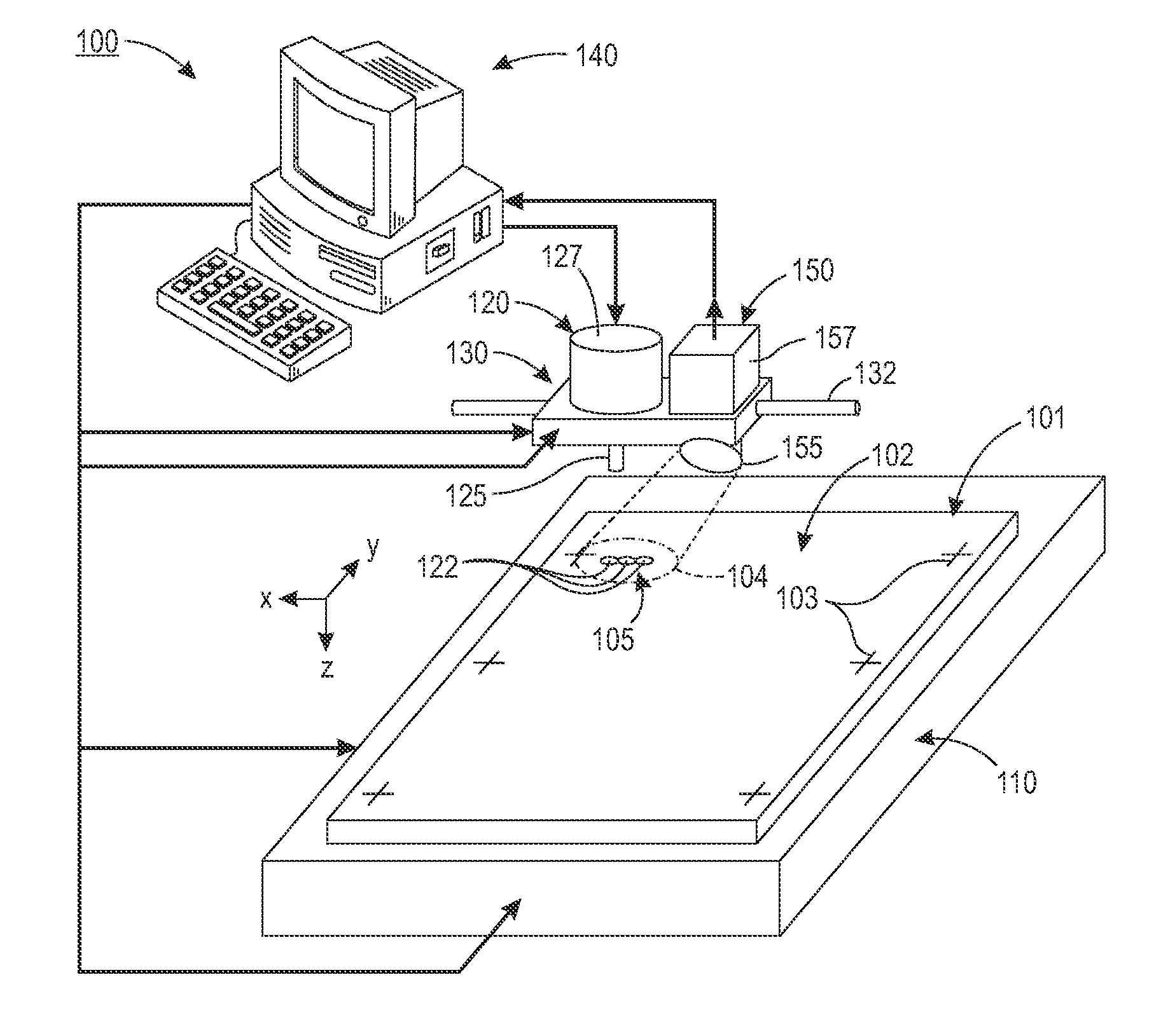
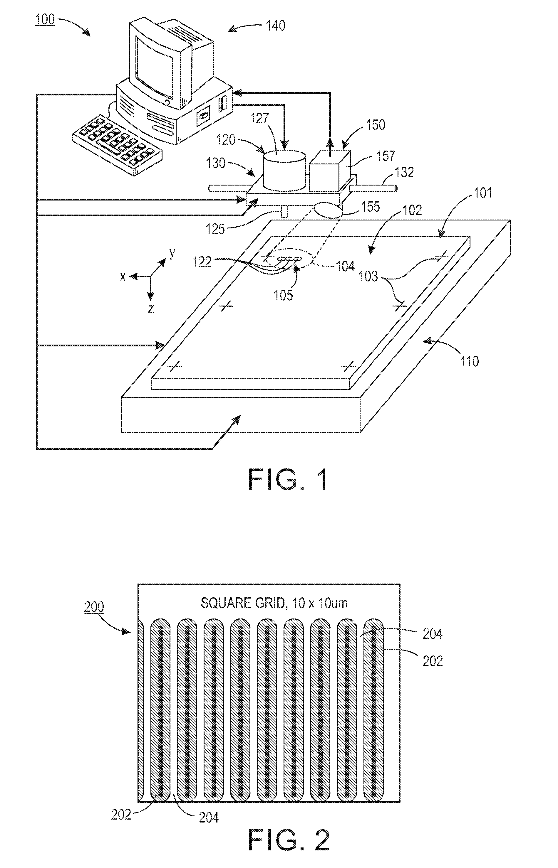
[0011]FIG. 1 illustrates a simplified digital lithography system 100 employed in an embodiment of the present application. Substrate 101 is placed or otherwise supported on a platen 110 below a drop source 120, which is suspended over platen 110 by way of a support structure 130. In a manner similar to conventional digital lithography systems, printing operations performed by drop source 120 are controlled by a digital control system 140 (e.g., a computer or other logic circuit programmed or otherwise configured to perform the various functions described herein). During these printing operations, drops 122 of appropriate material are ejected in the z-axis direction onto upper surface 102 of substrate 101 while substrate 101 and drop source 120 are moved relative to each other in the x-axis and / or y-axis directions, whereby printed features 105 are formed by contiguous drops 122 that are deposited and solidify on upper surface 102 of substrate 101.

[0012]Platen 110 and support structu...


PUM

PropertyMeasurementUnit
distanceaaaaaaaaaa
widthaaaaaaaaaa
widthaaaaaaaaaa

Abstract

A system and method is used to optimize print parameters in the printing of functional electronic materials and integrated objects. The method employs a grid pattern to determine drop spacing and further assigns priority to various features to be printed, separating features into layers to be printed. The most critical layers being printed with higher resolution and greater accuracy, the less critical layers being printed at lower resolution.

Description

BACKGROUND[0001]The present application is directed to digital lithography, and more particularly to improving the tuning and resolution of the same.[0002]With existing commercial digital printers, a design pattern is laid out on a grid, and each grid point designated by the design is then covered with material from the digital printers. The printed material administered from the digital printers is deposited on the desired surface in the form of drops at each grid point. This procedure does not take into account the importance of gap spacing and edge smoothness, two parameters important when printing electronics, especially for interconnect printing. For example, a typical digital printer prints narrow gaps by increasing the grid resolution and increasing the number of drops of dispensing. When printing electronics in this manner, the added drops required to increase printing resolution can lead to bridged gaps between the printed lines, causing undesired electrical short circuits....

Claims


Application Information

Patent Timeline
Patent Type & Authority Patents(United States)
IPC IPC(8): H05K3/12B41M5/00H05K3/00B41J2/00B41J2/04
CPCH05K3/125H05K3/1241B41M5/0023B41J2/04H05K3/00B41J2/00B41J2/2054G06K15/102B41J2202/04G06K15/1843
Inventor NG, TSE NGAMEI, PINGREADY, STEVEN E.
Owner XEROX CORP
Why Eureka
Try Eureka