Stereolithography apparatus

a stereolithography and apparatus technology, applied in the field of three-dimensional object printing, can solve the problems of large separation force, inability to resolve fine prints, and most important limiting factors of high-resolution printing, so as to improve print quality and speed, reduce build platform, and simplify the effect of printing machine structur

Active Publication Date: 2016-09-27
SYAO KAO CHIH
View PDF33 Cites 26 Cited by
  • Summary
  • Abstract
  • Description
  • Claims
  • Application Information

AI Technical Summary

Benefits of technology

[0010]The disclosure provides a stereolithography apparatus that overcomes the aforementioned major problems in existing arts. The stereolithography apparatus includes a supporting frame assembly, a tank, a vertically moving module, and a leveling ball joint, a build platform, and a digital light pattern generator. The tank is supported on the supporting frame assembly. The tank has an anchored portion anchored to the supporting frame assembly. The vertically moving module is fixed on the supporting frame assembly. The leveling ball joint is connected to the vertically moving module. The build platform is connected to the leveling ball joint and located over the tank, so as to be vertically moved relative to the tank by the vertically moving module. The digital light pattern generator is located under the tank. After a resin layer is solidified and adhered to the bottom of the tank and the build platform, the bottom of the tank starts being peeled away from a portion of the resin layer adjacent to the anchored portion. The tank partially moves upward freely relative to the supporting frame assembly around the anchored portion when the build platform moves away from the supporting frame assembly.
[0013]In an embodiment of the disclosure, the wall structure has a first side and a second side opposite to each other. The anchored portion is connected to an edge of the transparent bottom plate and extends outside the wall structure from the first side. The supporting frame assembly further includes a first retaining member and a second retaining member. The first retaining member is connected to the supporting body and located over the anchored portion. The second retaining member is connected to the supporting body and located adjacent to the second side. A distance between the first retaining member and the second retaining member is smaller than a distance between a distal end of the anchored portion and the second side, so that the tank is capable of rotating relative to the supporting body substantially around the first retaining member.
[0030]Accordingly, the stereolithography apparatus of the disclosure provides a passive self-peeling mechanism achieved by anchoring the anchored portion of the tank to the supporting frame assembly while allowing the tank to partially move upward freely relative to the supporting frame assembly around the anchored portion and thus eliminating the need of an extra actuator for tilting the tank downwards. Equipped with the above passive mechanism, the printer structure is simplified with only one vertical actuator to lift and lower the build platform. Moreover, the stereolithography apparatus of the disclosure further provides the transparent low surface energy protective film bonded on top of the impact resistant film which is bonded on top of the transparent elastic layer to protect the transparent elastic layer. As a result, the stereolithography apparatus of the disclosure is able to improve the print quality and speed, simplify the printer structure, enhance the printer reliability, and lower the printer cost.

Problems solved by technology

The magnitude of the separation force, which is positively correlated with the above forces and the size of solidified area, is one of the most important limiting factors for high resolution printing.
However, even with this improvement, the separation force is still too large to resolve fine prints.
Even though silicone does not form chemical bonds with most of the materials, silicone is not immune to attacks from more reactive resins under extensive UV and heat exposure.
Depending on the resin used, silicone can become blurred, deformed, or form strong bonds with the cured resin after a few thousand layers of printing.

Method used


Image

  • Stereolithography apparatus
  • Stereolithography apparatus
  • Stereolithography apparatus

Examples


Embodiment Construction

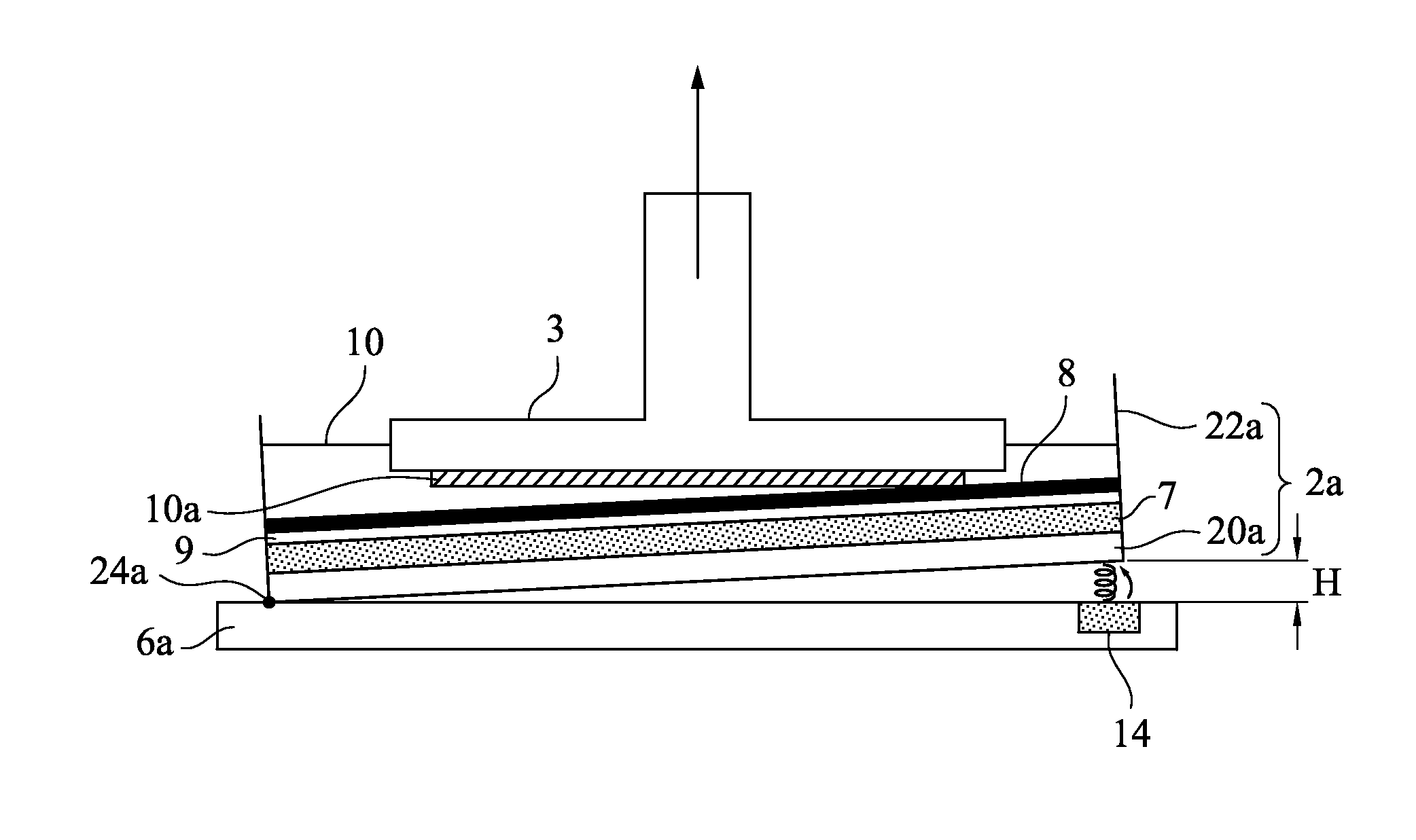
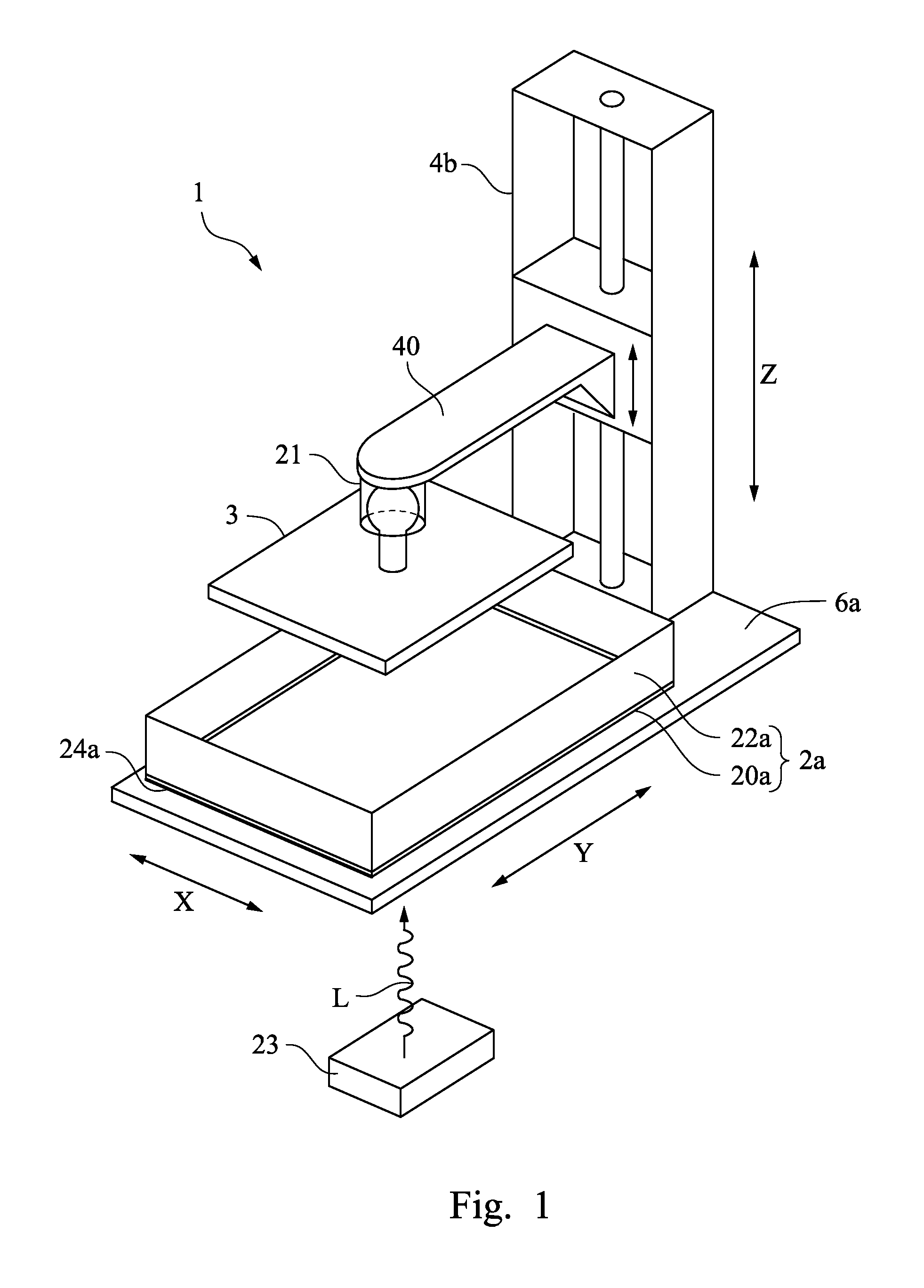
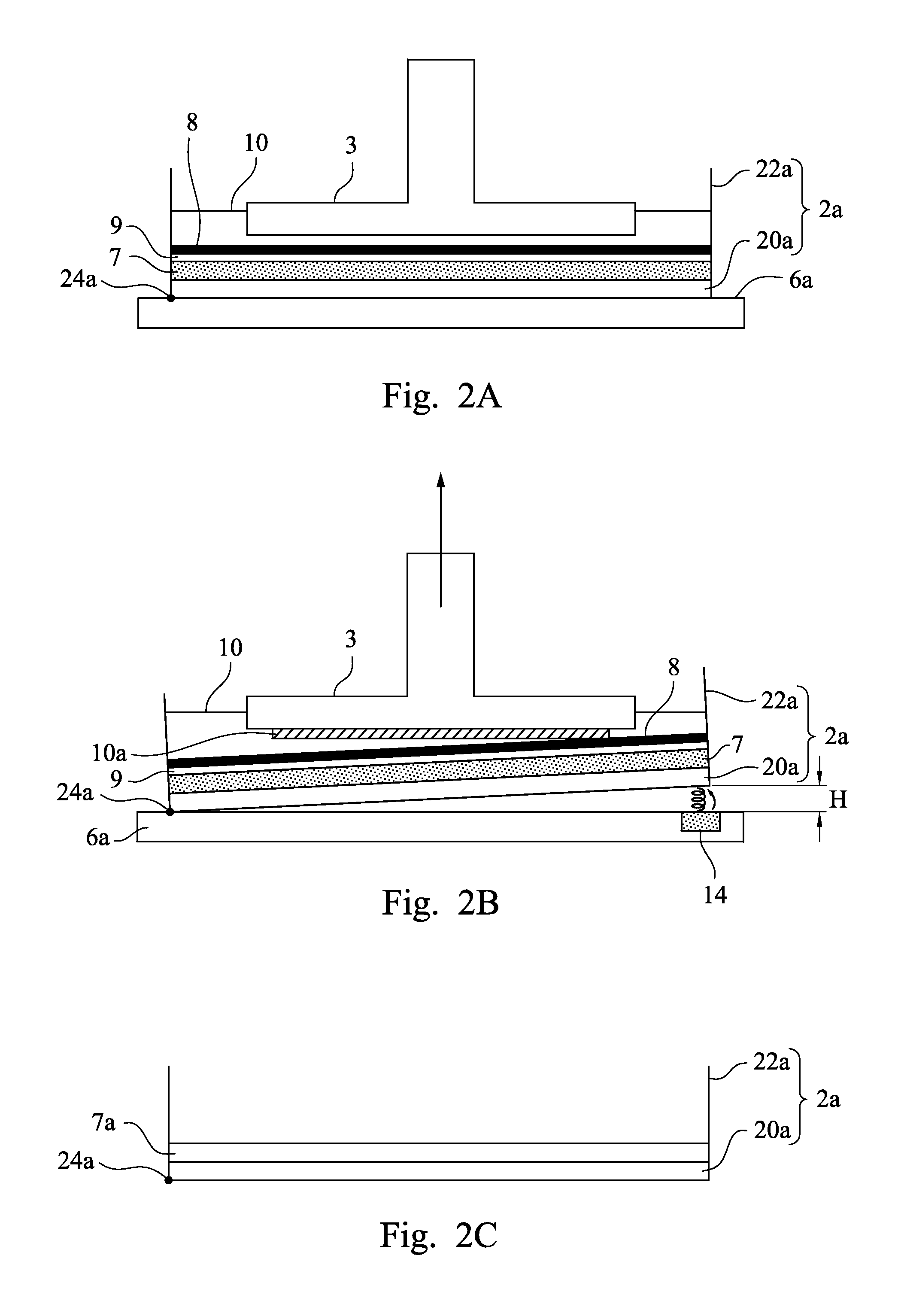
[0050]FIG. 1 is an axonometric view of a stereolithography apparatus 1 according to an embodiment of the disclosure. In the embodiment of the disclosure, the stereolithography apparatus 1 includes a supporting frame assembly, a tank 2a, a leveling ball joint 21, a build platform 3, a vertically moving module 4b, and a digital light pattern generator 23. The supporting frame assembly includes a supporting body 6a. The tank 2a is supported on the supporting body 6a. The tank 2a has an anchored portion 24a anchored to the supporting body 6a. The vertically moving module 4b is fixed on the supporting body 6a and connected to the build platform 3 through the leveling ball joint 21. The digital light pattern generator 23 is located under the tank 2a. In detail, the vertically moving module 4b includes a cantilever 40 extending over the tank 2a, and the leveling ball joint 21 is connected between the cantilever 40 and the build platform 3. The leveling ball joint 21 is able to provide a fa...


PUM

PropertyMeasurementUnit
thicknessaaaaaaaaaa
transparentaaaaaaaaaa
distanceaaaaaaaaaa

Abstract

A stereolithography apparatus includes a supporting frame assembly, a tank supported on the supporting frame assembly, a vertically moving module, and a build platform. The tank has an anchored portion anchored to the supporting frame assembly. The build platform is vertically moved relative to the tank by the vertically moving module. After a resin layer is solidified and adhered to the bottom of the tank and the build platform, the tank is peeled away from the resin layer starting from a portion of the resin layer adjacent to the anchored portion and partially moves upward relative to the supporting frame assembly around the anchored portion when the build platform leaves the supporting frame assembly. To further reduce the separation force between the cured resin layer and the tank, the bottom of the tank is covered with materials that are transparent, chemically resistant, impact resistant or / and elastic.

Description

RELATED APPLICATIONS[0001]This application claims priority to U.S. provisional application Ser. No. 61 / 870,668, filed on Aug. 27, 2013 and U.S. provisional application Ser. No. 61 / 979,537, filed on Apr. 15, 2014, which are herein incorporated by references.BACKGROUND[0002]1. Technical Field[0003]The present disclosure relates to three-dimensional object printing, and more particularly, the present disclosure is related to stereolithography for producing three-dimensional objects by solidifying photon curable liquid resin.[0004]2. Description of Related Art[0005]Stereolithography technology produces three-dimensional objects by stacking and adhering solid thin layers formed by photon curable liquid resins. Two-dimensional graphic layers are first generated by slicing the three-dimensional computer model of the object to be printed. These two-dimensional patterns are then projected to a liquid resin, usually photosensitive monopolymers, with light that has appropriate wavelength and e...

Claims


Application Information

Patent Timeline
Patent Type & Authority Patents(United States)
IPC IPC(8): B29C67/00B29K101/10B29K105/00
CPCB29C67/0062B29C67/0085B29K2101/10B29K2105/0058B29C64/124B29C64/25B29C64/255B33Y30/00B33Y70/00B29C64/245B29C64/264
Inventor SYAO, KAO-CHIH
Owner SYAO KAO CHIH
Why Eureka
Try Eureka