Electrical connector capable of suppressing crosstalk

a technology of crosstalk and electric connectors, applied in the direction of coupling device connections, coupling protective earth/shield arrangements, electrical apparatus, etc., can solve the problems of reducing the efficiency of signal transmission, interrupting signal transmission, extra signal interference, etc., to reduce the length of the straight path on the shield, effectively suppressing the antenna effect, and reducing the crosstalk effect between the signal terminals of adjacent terminal sets

Active Publication Date: 2016-09-27
ADVANCED CONNECTEK INC
View PDF28 Cites 0 Cited by
  • Summary
  • Abstract
  • Description
  • Claims
  • Application Information

AI Technical Summary

Benefits of technology

[0006]The present invention provides an electrical connector capable of effectively suppressing crosstalk between signal terminals and decreasing an antenna effect due to a shield with an entirely slice structure.
[0022]Each shield set is disposed on the lateral surface of the corresponding insulating portion in which the corresponding terminal set is disposed, so that the terminal sets and the shield sets are arranged in an interlaced manner. Moreover, each shield of the shield set can simultaneously shield the assembling section and the contacting section of the corresponding signal terminal of the terminal set, so that the crosstalk effect between the signal terminals of the adjacent terminal sets can be obviously decreased. In addition, the shields of the shield set are spacedly arranged, and each shield has at least one bending section. Comparing to the conventional single-slice shield shown in FIG. 8, the length of the straight path on the shield is decreased to effectively suppress the antenna effect which results in the extra signal interference, and further to suppress the crosstalk between the signal terminals to increase efficiency and stability of the signal transmission.

Problems solved by technology

However, crosstalk frequently happens between signal terminals of the electrical connector, especially in a situation of high-frequency signal transmission, and the crosstalk effect decreases the efficiency of signal transmission or interrupts the signal transmission.
However, the shield 82 is an entirely slice structure with a certain length and width, which easily provides a path with a certain length to transmit electric charges to result in an antenna effect to cause extra signal interference.

Method used


Image

  • Electrical connector capable of suppressing crosstalk
  • Electrical connector capable of suppressing crosstalk
  • Electrical connector capable of suppressing crosstalk

Examples


Embodiment Construction

[0032]The preferred embodiment of the present invention will now be further described below in detail in conjunction with the accompanying drawings. Wherever possible, the same or similar reference characters are used in the drawings and the description to refer to the same or like parts. For purposes of convenience and clarity only, directional terms, such as upper, lower, front, rear, forwardly, downwardly may be used with respect to the drawings. These and similar directional terms should not be construed to limit the scope of the present invention in any manner.

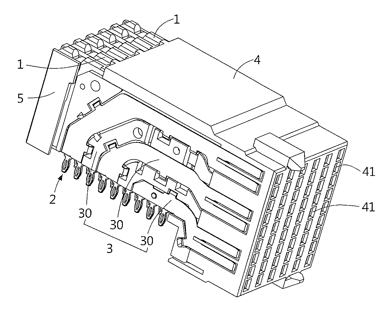
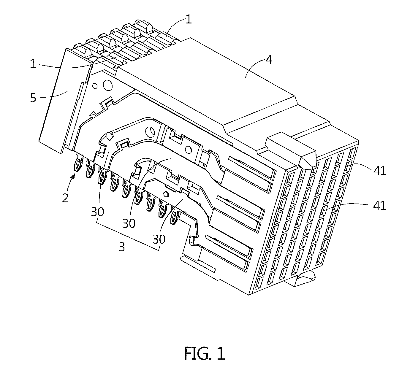
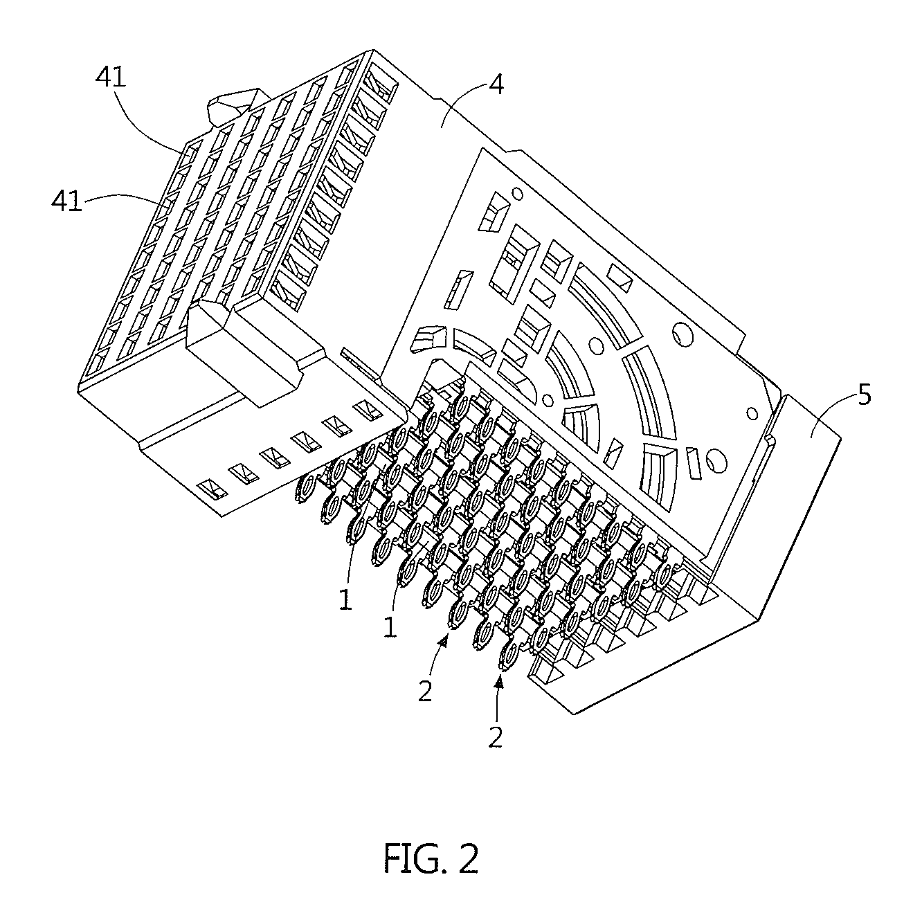
[0033]Please refer to FIG. 1 and FIG. 2. The present invention provides an electrical connector capable of suppressing crosstalk, which can be disposed on a circuit board (not shown) in a welding manner. The electrical connector includes a plurality of insulating portions 1, a plurality of terminal sets 2, a plurality of shield sets 3, a casing 4 and a cover 5.

[0034]Please further refer to FIG. 3 to FIG. 6. Each of the te...


PUM


Abstract

An electrical connector includes insulating portions arranged side by side, terminal sets, shield sets, and a casing. Each terminal set includes signal terminals and ground terminals. Each signal / ground terminal includes a fixing section disposed in the insulating portion, an assembling section downwardly stretching from the fixing section to protrude from the insulating portion, and a contacting section forwardly stretching from the fixing section to protrude from the insulating portion. Each shield set including shields is disposed on a lateral surface of the insulating portion. Each shield is spacedly arranged and connected to the ground terminal. Each shield includes a body section having at least one bending section, and a protrusion section protruding from the body section. The body section and the protrusion section shield the assembling section and the contacting section of the signal terminal respectively. It can effectively suppress crosstalk between the signal terminals by the shield sets.

Description

BACKGROUND OF THE INVENTION[0001]1. Field of the Invention[0002]The present invention relates to an electrical connector and, more particularly, to an electrical connector capable of effectively suppressing crosstalk between signal terminals.[0003]2. Description of the Prior Art[0004]A computer server, such as a blade server, a rack mount server and so on, includes multiple high-speed electrical connectors disposed on its internal circuit boards. The aforementioned electrical connector includes a plurality of terminals arranged intensively to rapidly transmit a large quantity of signals. However, crosstalk frequently happens between signal terminals of the electrical connector, especially in a situation of high-frequency signal transmission, and the crosstalk effect decreases the efficiency of signal transmission or interrupts the signal transmission.[0005]Please refer to FIG. 8, which illustrates an improved electrical connector to suppress crosstalk between its signal terminals. T...

Claims


Application Information

Patent Timeline
Patent Type & Authority Patents(United States)
IPC IPC(8): H01R13/648H01R13/6589H01R13/6587
CPCH01R13/6589H01R13/6587
Inventor LEE, KUO-CHINGWANG, YAO-TELIANG, YA-PING
Owner ADVANCED CONNECTEK INC
Why Eureka
Try Eureka