Method for solving antenna effect of cooling fin

An antenna effect and heat sink technology, applied in the electronic field, can solve the problems of serious radiation, difficult heat dissipation, increase R&D cost and production cost, etc., and achieve the effect of low radiation and reducing antenna effect.

Active Publication Date: 2019-06-11
JINGCHEN SEMICON SHENZHEN CO LTD
View PDF6 Cites 1 Cited by
  • Summary
  • Abstract
  • Description
  • Claims
  • Application Information

AI Technical Summary

Problems solved by technology

Moreover, in systems with ever-improving performance, the heat dissipation of the processing system is becoming more and more difficult. In order to ensure the safe and stable operation of the equipment, using metal heat sinks to dissipate heat for integrated chips has become the mainstream choice in the industry, but the introduction of improperly designed The metal heat sink will make the high-frequency signal in the system, such as the 2.97GHz radiation problem of the high-speed serial interface "V-By-One", the radiation problem is particularly serious, which significantly increases the product development cost and production cost

Method used


Image

  • Method for solving antenna effect of cooling fin
  • Method for solving antenna effect of cooling fin
  • Method for solving antenna effect of cooling fin

Examples


Embodiment Construction

[0046] The following will clearly and completely describe the technical solutions in the embodiments of the present invention with reference to the accompanying drawings in the embodiments of the present invention. Obviously, the described embodiments are only some, not all, embodiments of the present invention. Based on the embodiments of the present invention, all other embodiments obtained by persons of ordinary skill in the art without creative efforts fall within the protection scope of the present invention.

[0047] It should be noted that, in the case of no conflict, the embodiments of the present invention and the features in the embodiments can be combined with each other.

[0048] The present invention will be further described below in conjunction with the accompanying drawings and specific embodiments, but not as a limitation of the present invention.

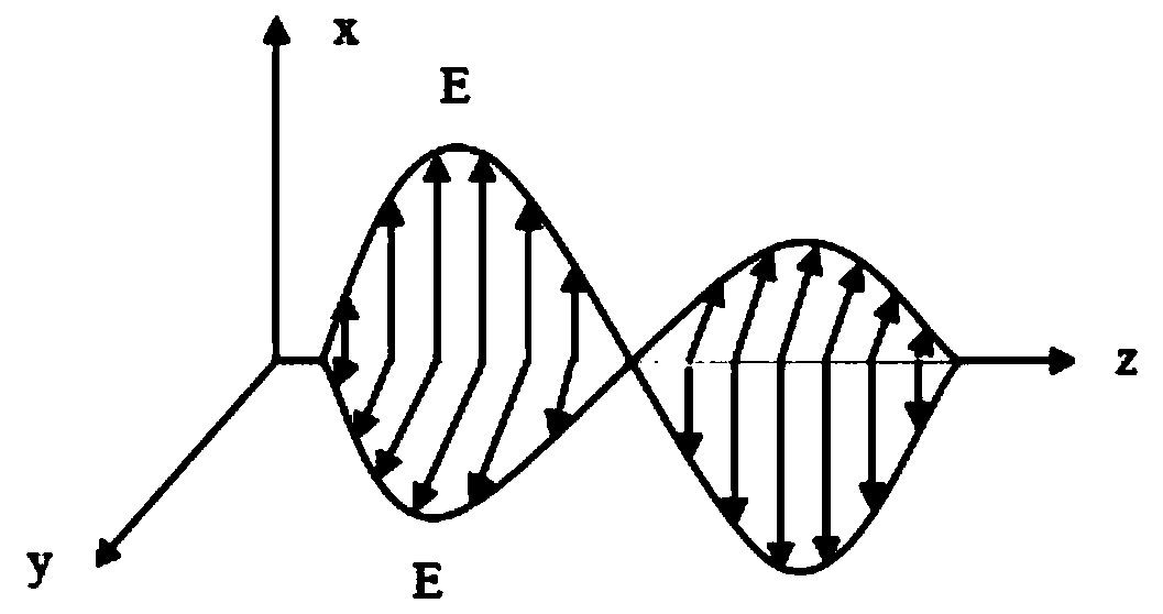
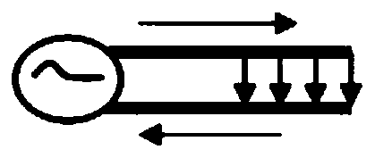
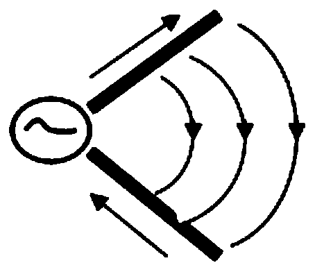
[0049] At present, electromagnetic waves propagate in the air in the form of mutual conversion between electric ...


PUM


Abstract

The invention relates to the technical field of electronics and particularly relates to a method for solving antenna effect of a cooling fin. The method comprises the steps of S1, providing an integrated chip and setting a heat conduction layer and a metal cooling fin on the integrated chip in sequence; and S2, adjusting thickness of the heat conduction layer to be unequal to a preset value, thereby reducing the antenna effect of the metal cooling fin. The technical scheme provided by the invention has the beneficial effects that an electromagnet interference method for solving the antenna effect is disclosed; the thickness of the heat conduction layer is adjusted to be unequal to the preset value, so the antenna effect of the metal cooling fin is reduced; a designer is assisted to designan H-shaped heat sink with low radiation; and an engineer is assisted to analyze an EMI (Electromagnet Interference) radiation problem of an electronic product.

Description

technical field [0001] The invention relates to the field of electronic technology, in particular to a method for solving the antenna effect of a heat sink. Background technique [0002] With the development of the electronics industry, the signal transmission rate of electronic equipment is getting higher and higher. For example, the 4K display interface on the market adopts the high-speed serial interface "V-By-One" mode transmission, and its data transmission rate has reached 2.97GHz , the electromagnetic interference (EMI, Electromagnet integrated chip Interference) radiation caused by this is particularly prominent. Moreover, in systems with ever-improving performance, the heat dissipation of the processing system is becoming more and more difficult. In order to ensure the safe and stable operation of the equipment, using metal heat sinks to dissipate heat for integrated chips has become the mainstream choice in the industry, but the introduction of improperly designed ...

Claims


Application Information

Patent Timeline
Patent Type & Authority Applications(China)
IPC IPC(8): H01L23/367H01L23/552
Inventor 韩小江尹秋峰张坤
Owner JINGCHEN SEMICON SHENZHEN CO LTD
Why Eureka
Try Eureka